26
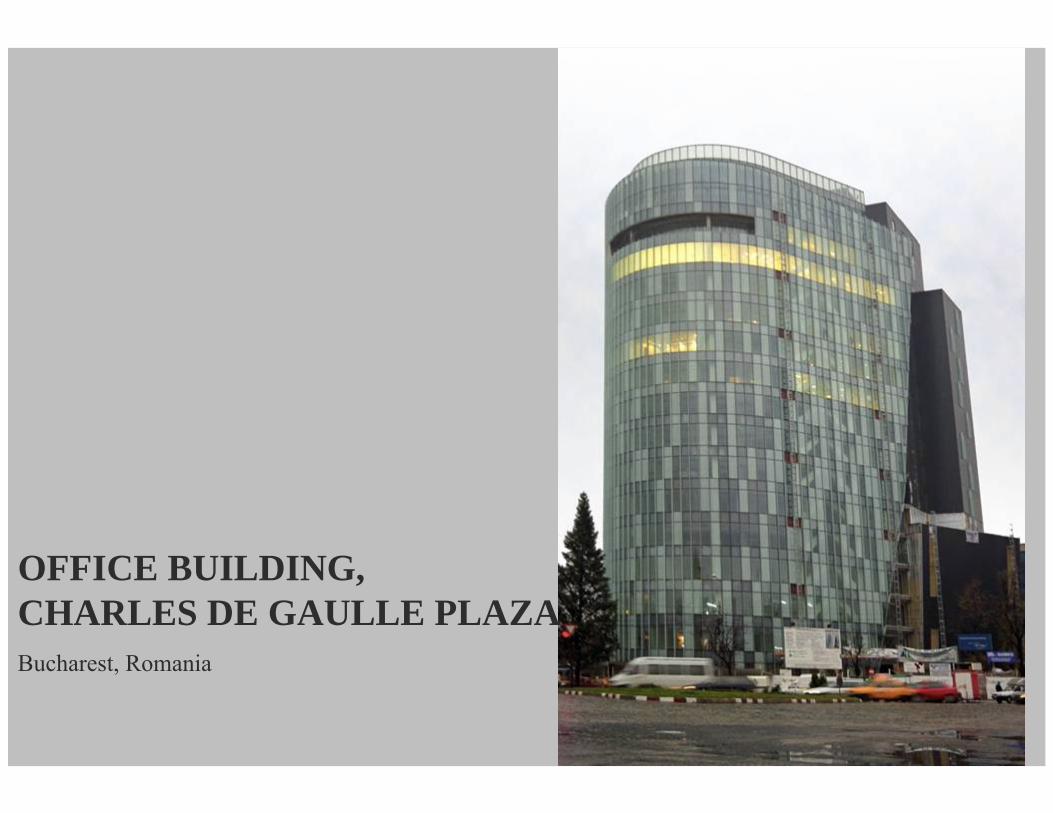
OFFICE BUILDING, CHARLES DE GAULLE PLAZA Bucharest, Romania
| Date post: | 08-Nov-2014 |
| Category: |
Documents |
| Upload: | mihaidelian |
| View: | 49 times |
| Download: | 8 times |
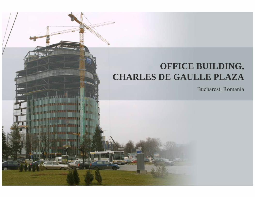
OFFICE BUILDING,CHARLES DE GAULLE PLAZA
Bucharest, Romania
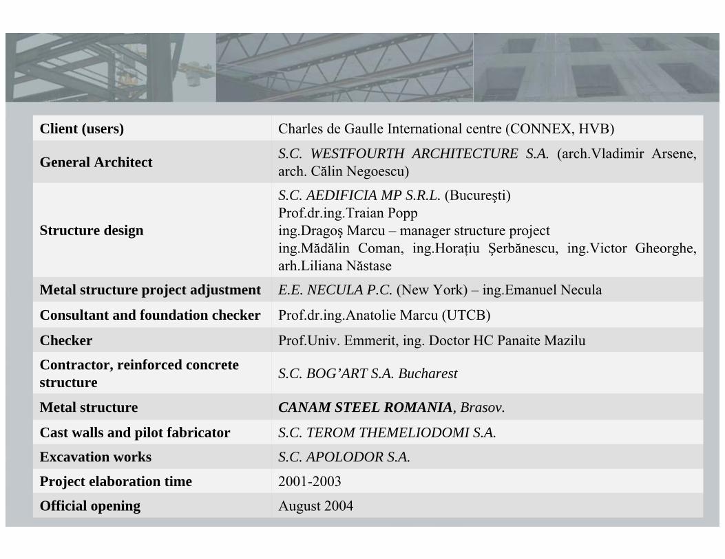
August 2004Official opening
2001-2003Project elaboration time
S.C. APOLODOR S.A.Excavation works
S.C. TEROM THEMELIODOMI S.A.Cast walls and pilot fabricator
CANAM STEEL ROMANIA, Brasov.Metal structure
S.C. BOG’ART S.A. BucharestContractor, reinforced concrete structure
Prof.Univ. Emmerit, ing. Doctor HC Panaite MaziluChecker
Prof.dr.ing.Anatolie Marcu (UTCB)Consultant and foundation checker
E.E. NECULA P.C. (New York) – ing.Emanuel NeculaMetal structure project adjustment
S.C. AEDIFICIA MP S.R.L. (Bucureşti)Prof.dr.ing.Traian Popping.Dragoş Marcu – manager structure projecting.Mădălin Coman, ing.Horaţiu Şerbănescu, ing.Victor Gheorghe, arh.Liliana Năstase
Structure design
S.C. WESTFOURTH ARCHITECTURE S.A. (arch.Vladimir Arsene, arch. Călin Negoescu)General Architect
Charles de Gaulle International centre (CONNEX, HVB)Client (users)
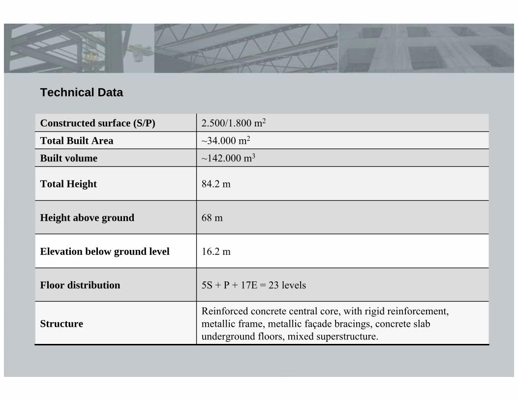
16.2 mElevation below ground level
68 mHeight above ground
84.2 mTotal Height
5S + P + 17E = 23 levelsFloor distribution
Reinforced concrete central core, with rigid reinforcement, metallic frame, metallic façade bracings, concrete slab underground floors, mixed superstructure.
Structure
~142.000 m3Built volume
~34.000 m2Total Built Area
2.500/1.800 m2Constructed surface (S/P)
Technical Data
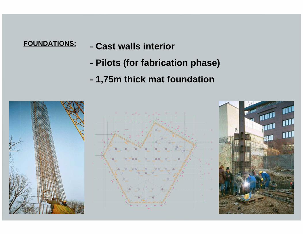
FOUNDATIONS: - Cast walls interior
- Pilots (for fabrication phase)
- 1,75m thick mat foundation
C227
C235s
300
300
P 21
PILOT TIP III d=1,50m.
3630
PILOT TIP I d=1,50m.
PILOT TIP III d=1,50m.
PILOT TIP II d=1,50m.
5183
7000.5
C310 P 30
705
4198.5
C320
705
705
P 28C310s
C310s PM 3C310
I 3
PILOT TIP II d=1,50m.
642 300300 7052652
705
PM 4
PILOT TIP IV d=1,50m.
P 26
C310
705
373.5C308.5
P 22
E 30x30 Ci=-1,00
C310d
100C320
PILOT TIP II d=1,50m.
P 24
43
29PILOT TIP II d=1,50m.
C310dC227P 20
C310
PILOT TIP IV d=1,50m.
28
PILOT TIP III d=1,50m.
42 PILOT TIP I d=1,50m.
PILOT TIP I d=1,50m.
P 3
PILOT TIP III d=1,50m.
27
C280d C280
PILOT TIP IV d=1,50m.
PILOT TIP II d=1,50m.
P 18C310d C310
20
21
P 16C235
P 14
5
PILOT TIP III d=1,50m.
P5
PILOT TIP I d=1,50m.
26
PILOT TIP III d=1,50m.
19
PILOT TIP IV d=1,50m.
7052366
328
PILOT TIP II d=1,50m.
1959
300
C310
s
705
P 32C310s
705C310
300
300
C205
C260
P 34
PILOT TIP II d=1,50m.
41
40
C310
655
P 36
C280
s P 38
PM 2
39
C182
.5
C280
P 39
C288
2282
.5
C320
s
730
730
C247.3 C 20
030052
2.5
PILOT TIP II d=1,50m.
PILOT TIP II d=1,50m.
P 1
PILOT TIP I d=1,50m.
PILOT TIP II d=1,50m.
38
36
34 32
PILOT TIP II d=1,50m.
33 31
300
730
PM 1
C235sP 35
35
I 1
C310
C310sP 37
C320
30
C320sP 33
P 31
Zona injectata
PILOT TIP II d=1,50m.
PILOT TIP II d=1,50m.
PILOT TIP II d=1,50m.
PILOT TIP I d=1,50m.
25
23
18 15
PILOT TIP II d=1,50m.
17 14
PM 7
22
C 20
0
C320
P 29
C320
s
PILOT TIP III d=1,50m.
16
45
13
Zona injectata
C320
P 27
300
C237.5C235
330300
PILOT TIP III d=1,50m.
44
P 25 C235sP 23
1792
P 06
B 300
712.
5
C310
d
712.
510
0
P 12 C3
10
E 30x30 Ci=-1,00
C310
d
C280
dPM
5P
08 B4
S 60x60 Ci=83,65(-1,75)
C310
P 10
P4
PILOT TIP I d=1,50m.
650
C280
C235
d30
030
0
C235
d
P 08
A
I 4
C235s
P 17 300
300
300
C235
d
C235s
300
300P
04 A
P 07
300
300
PILOT TIP III d=1,50m. 7PILOT TIP II
d=1,50m. P2 PILOT TIP III
d=1,50m.
PILOT TIP II d=1,50m.
PILOT TIP II d=1,50m.
PILOT TIP I d=1,50m.
12 3
10
S 60x60 Ci=82,65(-2,75)
P 06
A
C235
d
P 04
B
C235
d
2
PM 6
PILOT TIP III d=1,50m.
9
8
I 2P 15
PILOT TIP III d=1,50m.
6
1
C235s P 11
C235s P 13
C235s P 09
710
C300
s
P 01
65230
0C235
d
P 02
C300
d
300
298
C235
300
P 05
C205
.5
C235P 03
Zona injectata
C235s
300
300
C235s P 19
Zona injectii de proba
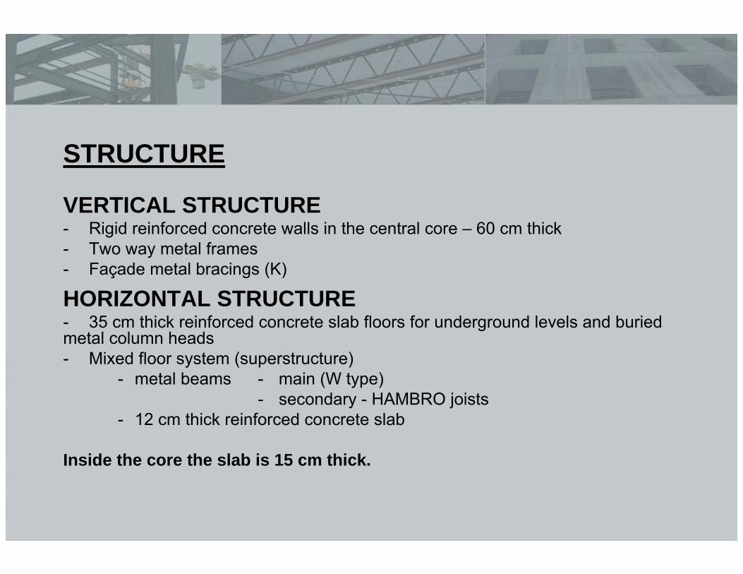
STRUCTURE
VERTICAL STRUCTURE- Rigid reinforced concrete walls in the central core – 60 cm thick- Two way metal frames- Façade metal bracings (K)
HORIZONTAL STRUCTURE- 35 cm thick reinforced concrete slab floors for underground levels and buried metal column heads- Mixed floor system (superstructure)
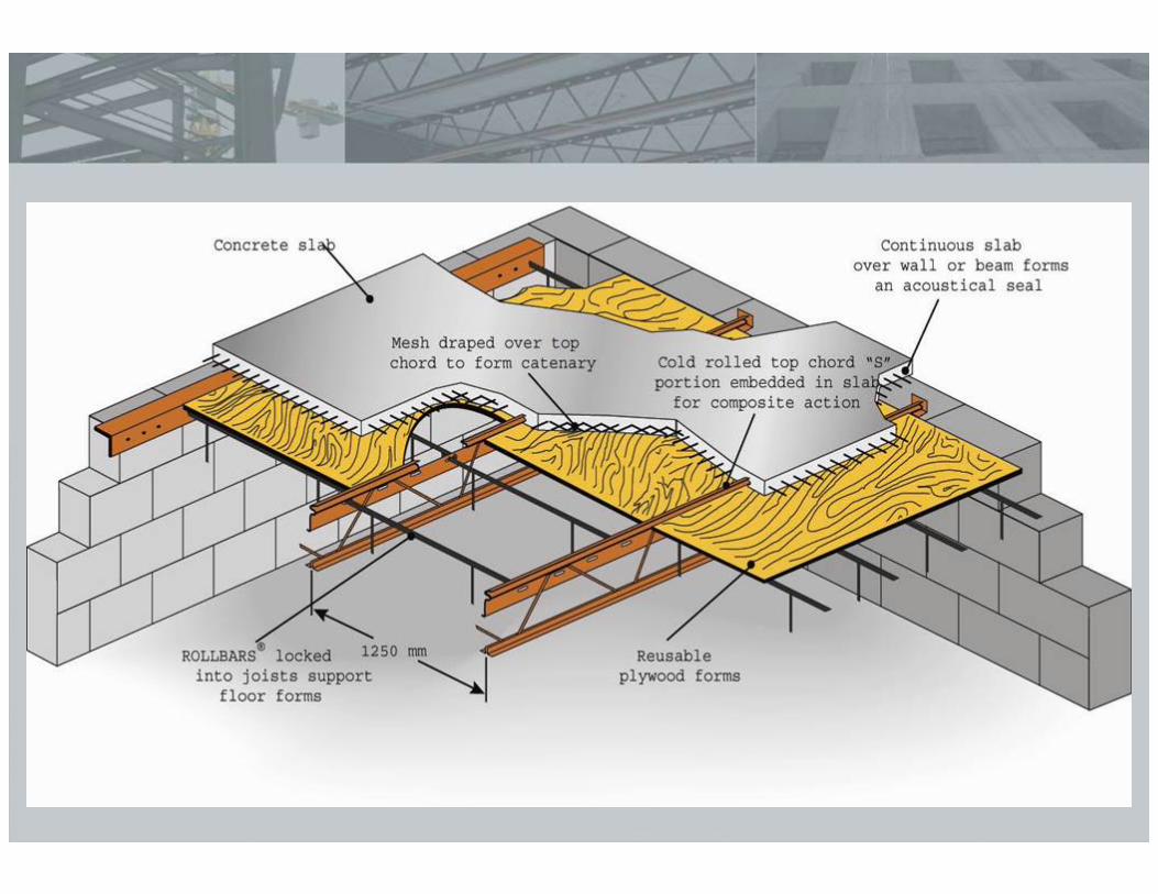
- metal beams - main (W type)- secondary - HAMBRO joists
- 12 cm thick reinforced concrete slab
Inside the core the slab is 15 cm thick.
5
7
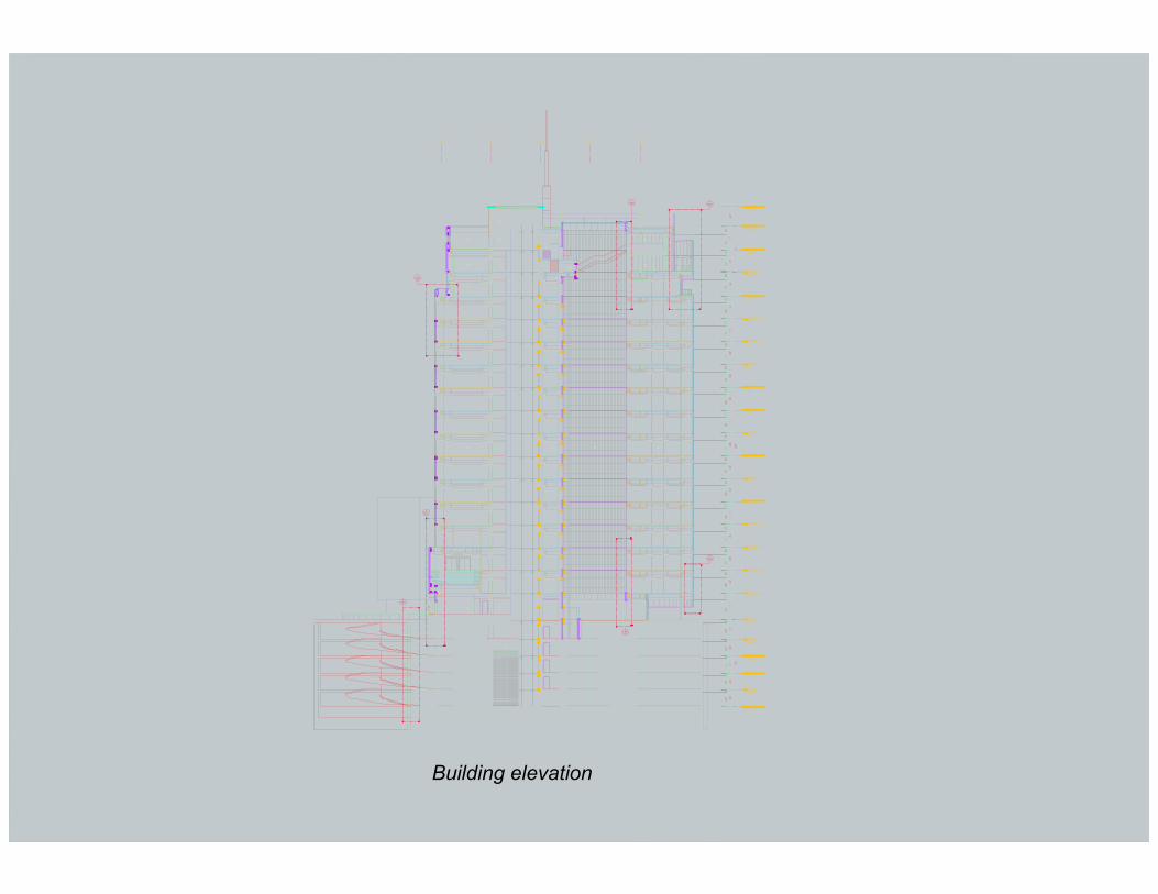
Building elevation
5.45
.15
.45
.30 .50.20.53
.45
.16
.20
.20.91
20x20
8
.21
.17
40.9
0
5.91
7.80 780 780 7.80 7.80 7.80 6.60220 560 5.60 2.20
.69
2.28
.49 10.22
10.1
61.
996.
36
2.10.95
4.44
.09
3.15
6.93
2.47
1.90
1.90
1.06
7.80
.55
1.26
18.1
30
5.75
5.58
.21
1.14
1.14
1.14
29°
61°
2.05
.64
.08
.64
.56
8.92
8.92
8.92
.90
1.25
220560 2.20 5.60
4.65
21
1.14
29°
29°
29°29°
29°
.49
.49
.09
.49
.60
2.55
.30
5.60
1.25
.69
0.65
75.5
2.10
4567
3.86.2
8'
4.25.8
D
E
3
2.2
F
F.5
2
1.8
8 19
4567 3 28 19
4.25.8 2.2 1.8
B
C
C.4
1'
A
4'3'
2'
A'
B'B'.2
C'
D'
E'E''
F'G'
K'.2
J'
I'
A.1
6.2 3.8
A
B
C
C.4
D
E
F.5
F
660
10x10
7.80
.69
7.11
.69 W610x230x113
W460x190x67
WP.2
W530x210x92
W61
0x23
0x12
5
W410x140x46.1
W610x230x140
W610x230x113
W61
0x23
0x10
1
W61
0x23
0x11
3
W46
0x15
0x52
SR
TC
SR
TC
SR
TC
SR
TC
SR
TC
SR
TC
SR
TC
SR
TC
SR
TC
SR
TC
SR
TC SR
TC
W53
0x21
0x10
1
SR
TC
SR
TC
SR
TC
SR
TC
WP.3
H300-10
H300-06
H400-12
H400-16
H200-03
H200-04
H300-08
H300-11
H300-08
H300-11H200-04
H400-12
H400-16
H300-10
H300-06
W310x100x28.3 W530x210x101
H25
0-04
H25
0-06
H25
0-08
H25
0-08
H25
0-08
H25
0-08
H25
0-06
H25
0-06
H25
0-04H
250-
06
H25
0-04
H25
0-06
H25
0-08
H25
0-08
H25
0-08
H25
0-08
H25
0-06
H25
0-06
H25
0-04
W53
0x21
0x10
1
W530x210x101 W310x100x28.3
H25
0-10
H40
0-15
H40
0-15
H40
0-13
H40
0-15
H40
0-15
H40
0-15
H20
0-04
H40
0-15
H40
0-15
H40
0-13
H40
0-15
H40
0-15
H40
0-15
H25
0-10
H20
0-04
W610x230x140
W610x230x101
W46
0x15
0x60
W25
0x10
0x17
.9
W25
0x10
0x17
.9
W460x150x52
W250x100x28.4
W250x100x17.9
W610x230x113
H30
0-12
H30
0-12
H30
0-12
H30
0-12
H30
0-12
H30
0-12
H30
0-12
H30
0-12
W41
0x14
0x46
.1
W610x230x101
W61
0x23
0x12
5
W25
0x10
0x17
.3
W25
0x10
0x17
.3
W25
0x10
0x17
.3W
250x
100x
17.3
W36
0x13
0x32
.9
W690x250x152
WP.1
1.00x2.30Ci=+8.15
1.00x2.30Ci=+8.15
1.00x2.30Ci=+8.15
.401.54.20
1.32
4.10 4.104.10 4.10
32.30
10.15
12.00
10.15
H400-16
H400-15
H40
0-13
H40
0-13
H40
0-15
H40
0-13
H40
0-15
H40
0-15
H400-15
H400-15
H400-15
H400-15
H400-15
H400-15
H400-15
H400-15
H400-15
H400-15
H400-15
H400-15
H400-15
H400-15
H400-15
H400-15
H400-15
.60
7.20
.60
8.19
.60 30.60 .607.50
16.73
1.14
5.58
1.94
8.92
8.92
8.92
35.41
3.91
20.430
.115
12.595
6.82
.90
22.21
4.45
27.79
.12
.12
.12
.12
.12
.12
2.45
7.80
7.80
7.80
1.57
8.05
2813
122°
38.325° 38.325
°
1.201.201.201.00x2.30Ci=+8.15
.69
.69
.69
.35
1.25
.95
.12
.12
.12
.12
.12.1
2
.12
.12
.12.12
.12
.12
.12
.12
.12
.12
.12
.12
.12
.12
.12
.12
.12
.12
.12
.12
.12
.12
.12
.12
.12
.12
.12
.12
.12
.12
.12
.12
10.1
1.12
.12
.12
.12
.12
.12
.12
.12
.12
.12
.12
.12
.39
.12
.12
.12.12 .12 .12
R14.
527
4.40
10x10
30x40
20x40
.10.29
.10.38
.86.30
.12.12
.44
.44
1.03
.69 4.40 5.60 5.60 2.20 2.202.63
.12
5.11 5.11
5.81
4.35
11.80
.72
36.72
.10.25
.10.49
8
8
11.22
16.56
.12
4.32
3.91
1.76
7.50 8.
19
7.50 31.80 9.78
+11.95
+11.95
+11.
95
+11.
95
+11.95
+11.95 +11.95
+11.95
+11.
95+1
1.95
.29
.12 .12.12 .12
H400-12
W360x130x32.9
W41
0x14
0x46
.1
W41
0x14
0x46
.1
W41
0x14
0x38
.8
W31
0x16
5x31
W53
0x21
0x92
W41
0x14
0x38
.8
W360x130x32.9
W31
0x10
0x21
W410x140x46.1
W610x230x101
W360x130x39
W46
0x15
0x52
RTC
H400-12
H400-12
H400-08
W310x100x21
W310x100x21
W360x130x32.9
H200-04
H300-11
H400-12
RTC
W310x100x21
H40
0-14
H40
0-12
RT
C
W530x210x92
RT
C
W310x100x32.7
W46
0x15
0x52
W36
0x13
0x39
W31
0x10
0x32
.7
H20
0-04
W460x150x52
W460x150x60
W250x100x28.4
W250x100x25.3
W310x100x32.7
W360x130x32.9
SR
TC
SR
TC
W610x230x140
W610x230x140
H30
0-10
H35
0-11
H40
0-11
W460x190x67
W310x100x21
W46
0x19
0x97
W36
0x13
0x39
W46
0x19
0x97
W46
0x19
0x97
W360x130x39 W360x130x39 W360x130x39
W360x130x39 W360x130x39
W360
x170
x44
W610x230x101
W360x130x32.9
W360x170x44
W360x170x44
H20
0-12
H20
0-14
W360x170x44
W41
0x14
0x46
.1
W610x230x101
H20
0-14
H20
0-08
W360x130x32.9
W250x100x22.3(TYP.)
W250x100x22.3
(TYP.)
W360x130x32.9
H40
0-13
H40
0-13
H40
0-15
H40
0-13
W31
0x10
0x28
.3
H40
0-15
W31
0x13
0x32
.9
W31
0x13
0x32
.9
H30
0-11
H20
0-04
RTC
W360x130x39
W360x130x32.9
W310x100x32.7
56100
34
156
106
H40
0-18
H400
-12
W410x150x52
1.785
34
45678
3.86.2
8'
4.25.8
A
B
C
D
E
C.4
A'
23 1
1'
4'
3'
2'
B.5
A.2
A.6
AX
AY
150
390
460
150
390
150
390
150
369
390
150
224
150
306
446
446
446
446
446
150
352.5645
360
237.5237.5352.5
300
150
460
460
150
460
150
8030
300
7025 70 25 70
25 70
5
70
12.5
305
80
305
80
305
80
100
7067.5
432
432
432
436
6988
859 2035.5
780660 780 780 780 780 780 660
220 220560 560 220220 560560
119°
90°
1615
.588
9
6092
.5
4415
1677
.5
780
780
315
780
780
465
5183
4198.5
775
970
390
390
1067.5 3026
475
577
682
6823632.5
2285.5
532.
595
7
250
30
2205
.5
3588
1959
453.
548
018
0
92°
91°
90°
123°
119°
S3HD 400x314 S3
HD 400x314
S1HD 400x634
S1HD 400x634
R100R100
R100R100
R100
R100
R10 0
R100
R100R100
R100
R100
R100
R100
R100
R100
400
227
400
436
98.5
120
90
100
100
120
100
120
100
100120
100120
120
100
100
340
120
100
120
100
100120
100120
100
100
120
100
120
120
120
100
100120
100
30
100
98.5
100
98.5
98.5
98.5
100
8810
0
100
88
8810
0
100
88
100
123
123
123
100
123
100
123
100
100
123
100
123
123
123
100
123
100
100
123
100
123
100
120
100
100
100
100
100
106.5
81
77.5 67.5100100 77.5 77.5 10077.510086.510086.5 10086.5 10086.567.5 10077.5 77.5 100 77.5 100 10077.5 86.5 100 86.5 100
100100
100
100
100
100
107.5
100100
100
100
77
69
100
10069
100
100100
77
100
77
69
100
10069
100
77
100
100
100
77
10069
100
69
100
10077
100
100
100
100
66.575.5
5010
6.5
106.
5
100
100
106.
5
100
106.
5
106.
5
100
100
100
106.
5
100
106.
5
106.
5
100
106.
5
50
5090.5
100107
70
70
120
104
100
90.5
100
90.5
90.5
100
100
90.5
100
100
90.5
80
90.5
90.5100
120
100
100
100
120
100
120
95
125
120
35
10030
120
74
100
100
35
50
6550 64.5
S3HD 400x314 S3
HD 400x314S3
HD 400x314
S3HD 400x314
S3HD 400x314
S3HD 400x314
S3HD 400x314
S3HD 400x314
S3HD 400x314
S3HD 400x314
S3HD 400x314
S3HD 400x314
S3HD 400x314
S3HD 400x314
S3HD 400x314
S2HD 400x421
S2HD 400x421
S3HD 400x314
S3HD 400x314
S2HD 400x421
S2HD 400x421
S2HD 400x421
S2HD 400x421
GOLTEHNOLOGIC
GOLTEHNOLOGIC
GOLTEHNOLOGIC
GOLTEHNOLOGIC
GOLTEHNOLOGIC
GOLTEHNOLOGIC
GOLTEHNOLOGIC
GOLTEHNOLOGIC
GOLTEHNOLOGIC
GOLTEHNOLOGIC
700
50
GOLTEHNOLOGICGOL
TEHNOLOGIC
GOLTEHNOLOGIC
GOLTEHNOLOGIC
GOLTEHNOLOGIC
GOLTEHNOLOGIC
GOLTEHNOLOGIC
200
700
20 3180 20
2084
020
20318020
2084
020
3220
880
VEZI PLANSA R2.12
GOLTEHNOLOGIC
65
92.5 102.5
65
753062.5 30
401.
5
401.
5
R470R500
R1150R1180
R470
R47
0
67.5
71.565
706
305
80
29.5
R500
90
240
145.5
485
733
60 50.550.5
2388
R1180
336.
5
1038
239
288
32.5
336.
5
70 12.5
70 12.5
7070
198
12.5
141
535
168
168
288
60
39
39
65
37.5
67.5
340
2652
R40
R40
R40
R40R40
R40
R40
R40
R40
R40
R40
R40R40
R40
R40
R40
R40
60
1180310 65 430 65 310
90 90
9090 9090
90
90
90 180
160
90
90
160
50 45
35
30
40
4540
40
35
90
160
58
40
58
40
50
37.5 37.5
14
35
50
50
60
3030S-Ø200
S-Ø200S-Ø100
50
3030S-Ø200
S-Ø200S-Ø100 S-Ø150
S-Ø200S-Ø200 S-Ø1003030
S-Ø200
S-Ø200
S-Ø100
S-Ø200
S-Ø200
S-Ø100
S-Ø200
S-Ø100
S-Ø200
S-Ø100
S-Ø200
S-Ø200
S-Ø200S-Ø200
S-Ø100
265
S-Ø200
S-20x20Ci=-6,70(-9,50)
varia
bil
varia
b il
-6.0
5 (-8
.85)
-6.4
0 (-9
.20)
-6.40 (-9.20)
-6.05 (-8.85)
-6.05 (-8.85)
-6.40 (-9.20)
-6.40 (-9.20)
-6.05 (-8.85)
-6.0
5 (-8
.85)
-6.4
0 (-9
.20)
650
20.5
53
15
ROST DE TURNARE
ROST DE TURNARE
Tabla expandata
ROST DE TURNARE
ROST DE TURNARE
ROST DE TURNARE
ROST DE TURNARE
ROST DE TURNAREZona superioara a rampei se toarna( dupa efectuarea sapaturii locale) in acelasi timp cu planseul superior.Zona inferioara se toarna, dupa excavarea nivelului inferior, inaintea turnarii planseului inferior.
8,2%
Tabla expandata
Tabla expandata
Tabla expandata
242.
5
30
453
245.5
25
100
250
175
250
25
100x100-8.85
100x100-6.05
R2.196
R2.197
R2.194
50
165
636
636
23°23°
10R2.19
6R2.19
10R2.19
11R2.19 In rampa
In planseu
R2.195
6R2.19
S3HD 400x314
R2.198
7,5%
-6.05 (-8.85)
720
varia
bil
varia
bil
R2.194
77 177.5 177.5 177.5 182 186.5 186.5 186.5 186.5 186.5 182 177.5 177.5 177.5 77 125
203
200
210
221.5
223
223
223
223
223
223
223
223
223
223
223
205.
5
188
188
188
193.
5
198.5
198.
5
198.
584
.5 85
210
220
220
220
220
220
220
220
220
200
220
220
220
95 60
183.
5
200
210
220
220
232.
5
32
142.5
157.5
190.5
193.5
190.5
190.5
190.5
190.5
197.5
182
183.5
198.5
77
88.5
206.
5
206.
5
206.
5
206.
5
206.
5
206.
5
206.
5
206.
5
96
95
188
200
188.5
173
169
173
188.5
188.5
173
169
173
188.5
188.5
173
169
173
188.5
200
200
200
200
148 .5
200
260
207.
5
220
220
197
10
10
10
10
10 10
10
10
10
10
10
801
1
87.587.5
-6.0
5(-8
.85)
-6.4
0(-9
.20)
100
255
315
8.2%
7.5%
8.2%
233
233
3' 4'
Stalp ax A'/3' Stalp ax A'/4'
niv. rampa var.
niv. grinda var.558.5
81.5
8 1. 5
R2.196
R2.198
R2.197
R2.1910
R2.1911
SECTIUNEA 1-1
-6.05(-8.85)
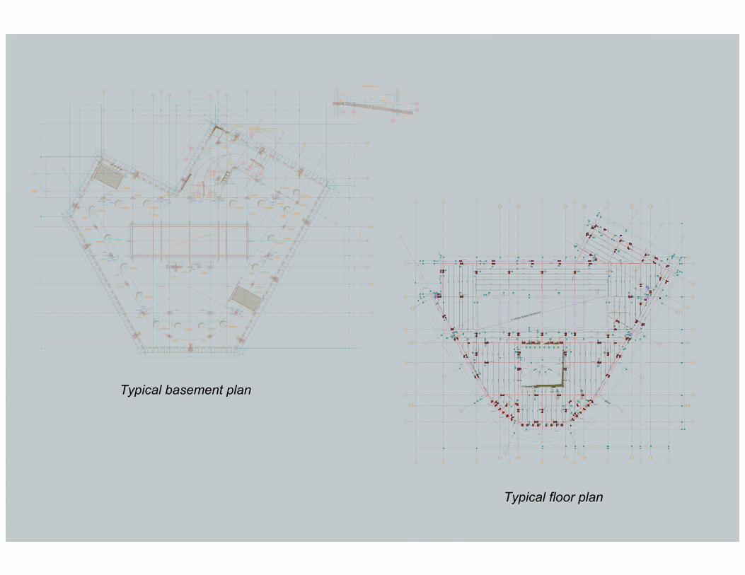
Typical basement plan
Typical floor plan
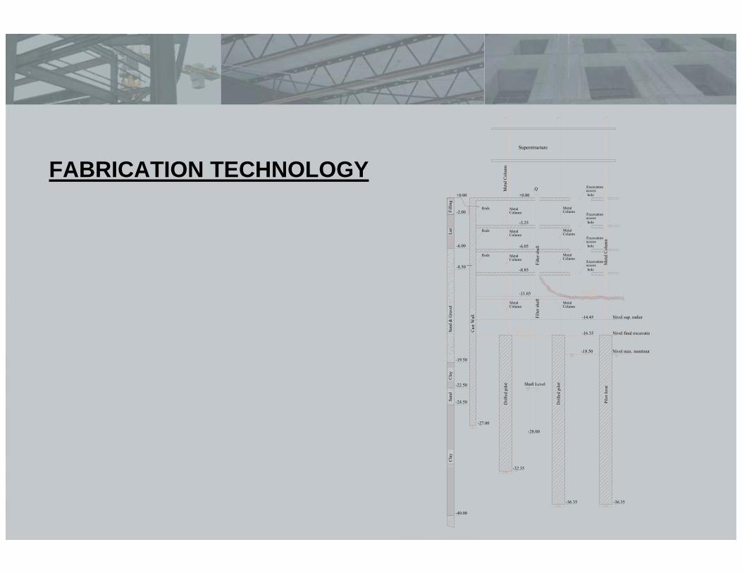
FABRICATION TECHNOLOGY+0.00
-2.00
-6.00
-19.50
-22.50
-24.50
-40.00
-27.00
Cla
ySa
ndC
lay
Sand
& G
rave
lLu
tFi
lling
Cas
t Wal
l-32.35
-36.35D
rille
d pi
lot
Dril
led
pilo
t
-36.35
Pilo
t for
at
-28.00
Filte
r sha
ft
+0.00
-3.25
-6.05
-8.85
-11.65
-14.45
-16.35
-18.50 Nivel max. mentinut
Nivel final excavatie
Nivel sup. radier
Ø1500Ø1500
Ø1500
Filte
r sha
ft
-8.50± 1.00m(HH)
80
Rods
Met
al C
olum
n
Superstructure
Met
al C
olum
n
Q
Shaft Level
Rods
Rods MetalColumn
Excavationaccess hole
MetalColumn
MetalColumn
MetalColumn
MetalColumn
MetalColumn
MetalColumn
MetalColumn
Excavationaccess hole
Excavationaccess hole
Excavationaccess hole
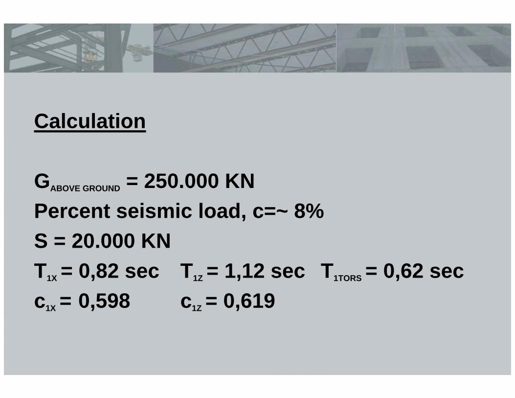
Calculation
GABOVE GROUND = 250.000 KNPercent seismic load, c=~ 8%S = 20.000 KNT1X = 0,82 sec T1Z = 1,12 sec T1TORS = 0,62 secc1X = 0,598 c1Z = 0,619
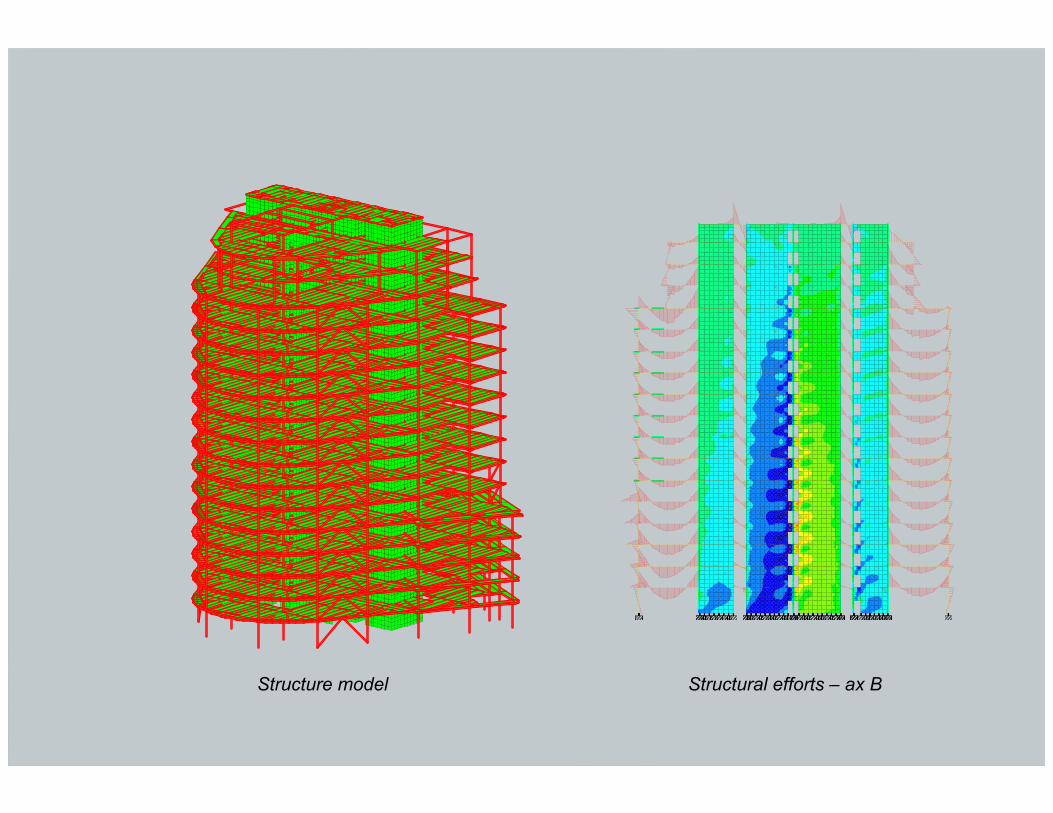
Structure model Structural efforts – ax B
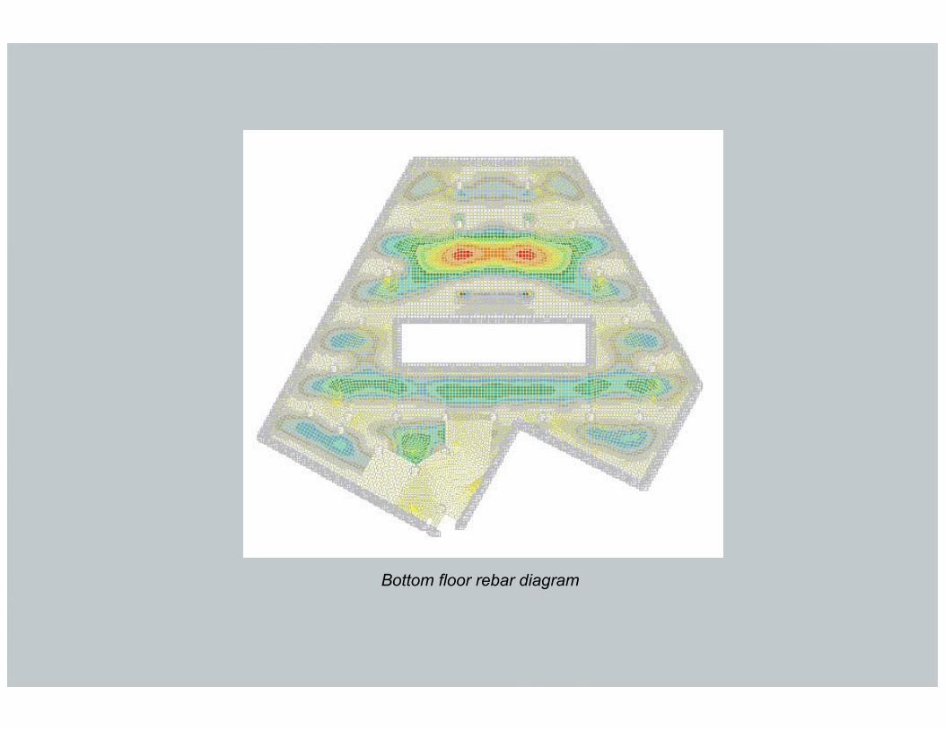
Bottom floor rebar diagram
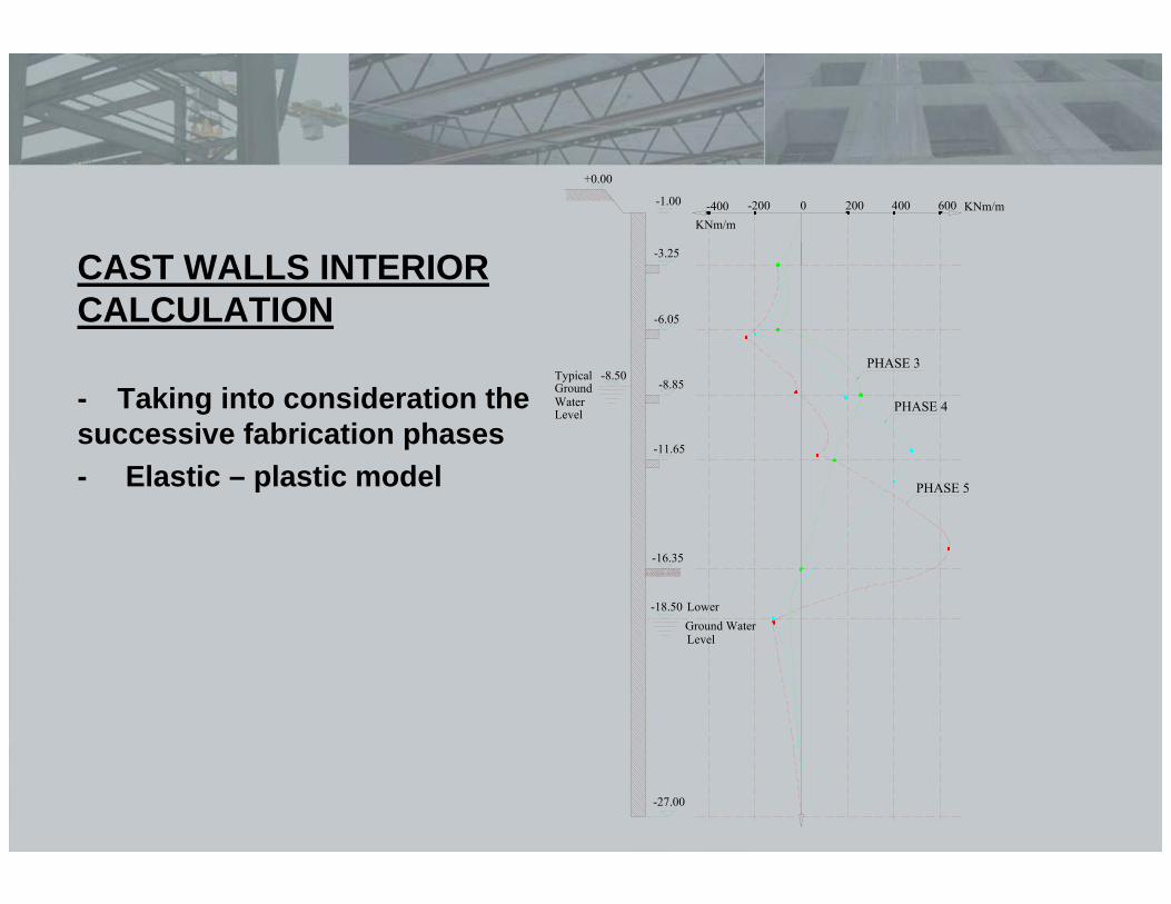
CAST WALLS INTERIOR CALCULATION
- Taking into consideration the successive fabrication phases- Elastic – plastic model
+0.00
-1.00
-3.25
-6.05
-8.85
-11.65
-16.35
-18.50
-27.00
-8.50
0 200 400 600-200-400 KNm/mKNm/m
PHASE 3
PHASE 4
PHASE 5
LowerGround WaterLevel
TypicalGroundWaterLevel
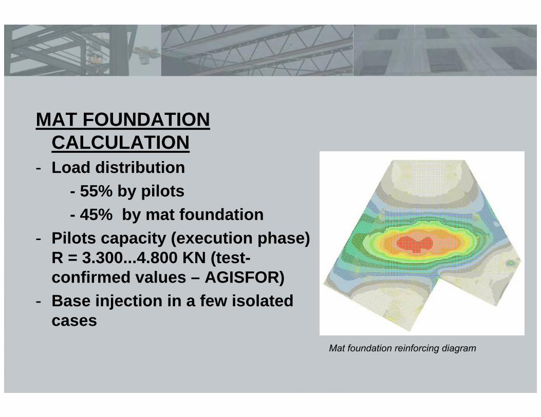
MAT FOUNDATION CALCULATION
- Load distribution- 55% by pilots- 45% by mat foundation
- Pilots capacity (execution phase)R = 3.300...4.800 KN (test-confirmed values – AGISFOR)
- Base injection in a few isolated cases
Mat foundation reinforcing diagram
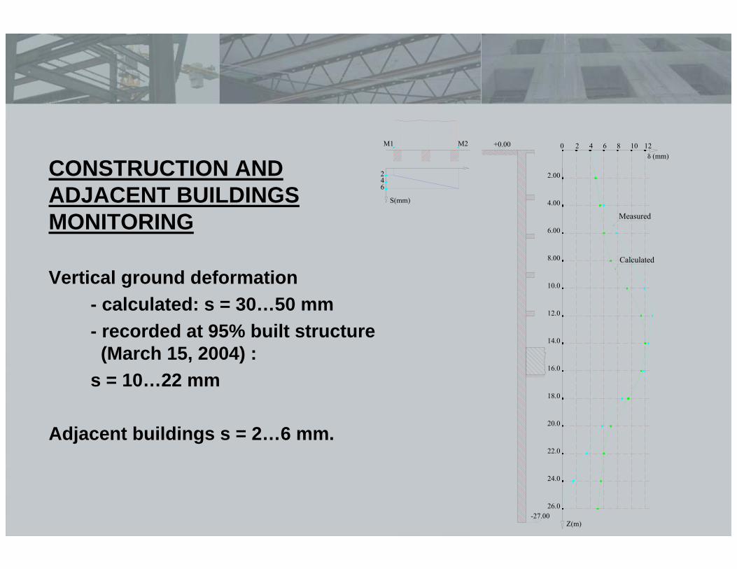
CONSTRUCTION AND ADJACENT BUILDINGS MONITORING
Vertical ground deformation- calculated: s = 30…50 mm- recorded at 95% built structure (March 15, 2004) :
s = 10…22 mm
Adjacent buildings s = 2…6 mm.
+0.00
-27.00
0M2M1
246
S(mm)
2.00
4.00
6.00
8.00
10.0
12.0
14.0
16.0
18.0
20.0
22.0
24.0
26.0
Z(m)
2 4 6 108 12δ (mm)
Measured
Calculated
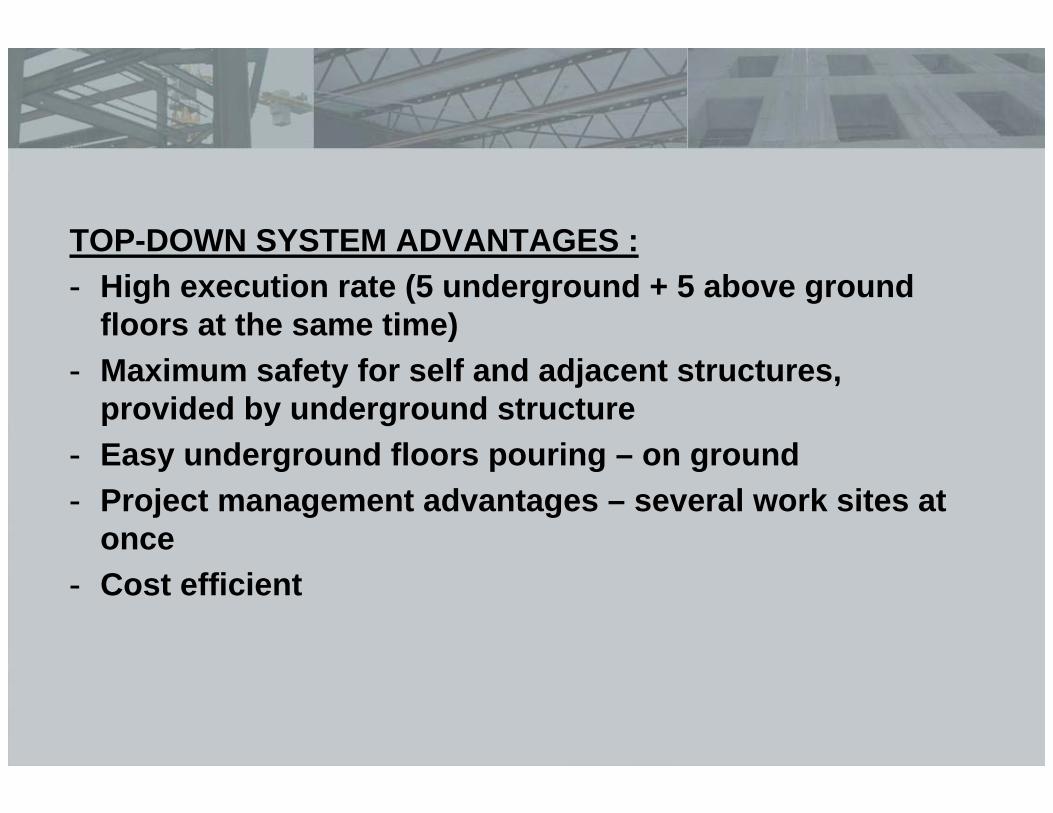
TOP-DOWN SYSTEM ADVANTAGES :- High execution rate (5 underground + 5 above ground
floors at the same time)- Maximum safety for self and adjacent structures,
provided by underground structure- Easy underground floors pouring – on ground- Project management advantages – several work sites at
once- Cost efficient
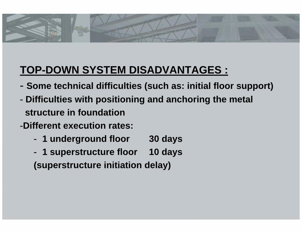
TOP-DOWN SYSTEM DISADVANTAGES :- Some technical difficulties (such as: initial floor support)- Difficulties with positioning and anchoring the metal structure in foundation
-Different execution rates:- 1 underground floor 30 days- 1 superstructure floor 10 days(superstructure initiation delay)
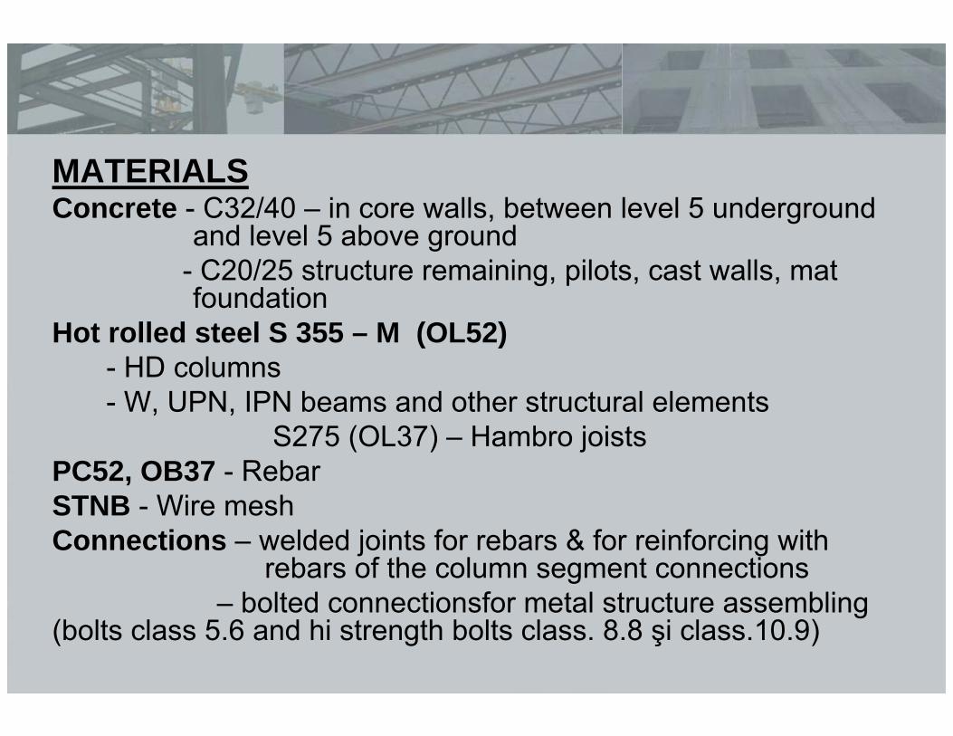
MATERIALS Concrete - C32/40 – in core walls, between level 5 underground
and level 5 above ground- C20/25 structure remaining, pilots, cast walls, mat foundation
Hot rolled steel S 355 – M (OL52)- HD columns- W, UPN, IPN beams and other structural elements
S275 (OL37) – Hambro joistsPC52, OB37 - RebarSTNB - Wire meshConnections – welded joints for rebars & for reinforcing with
rebars of the column segment connections– bolted connectionsfor metal structure assembling
(bolts class 5.6 and hi strength bolts class. 8.8 şi class.10.9)
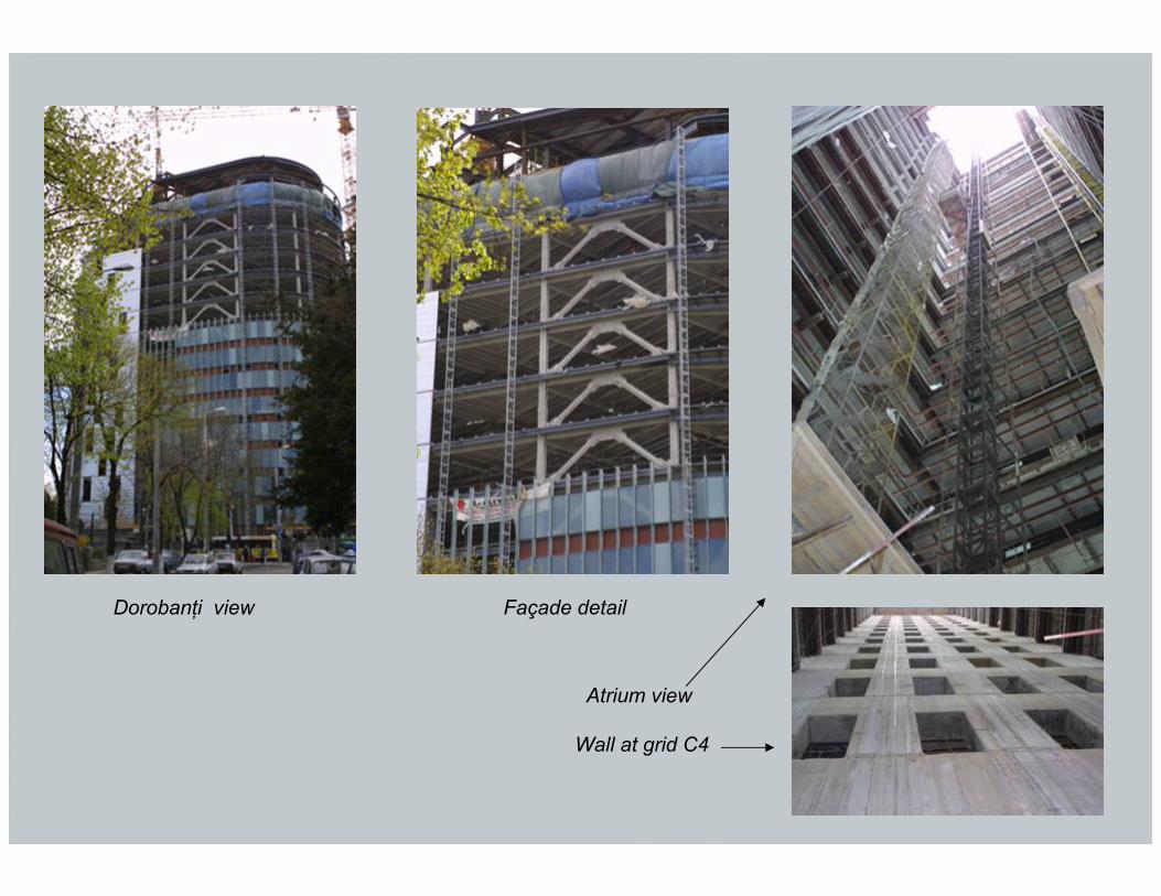
Dorobanţi view Façade detail
Atrium view
Wall at grid C4
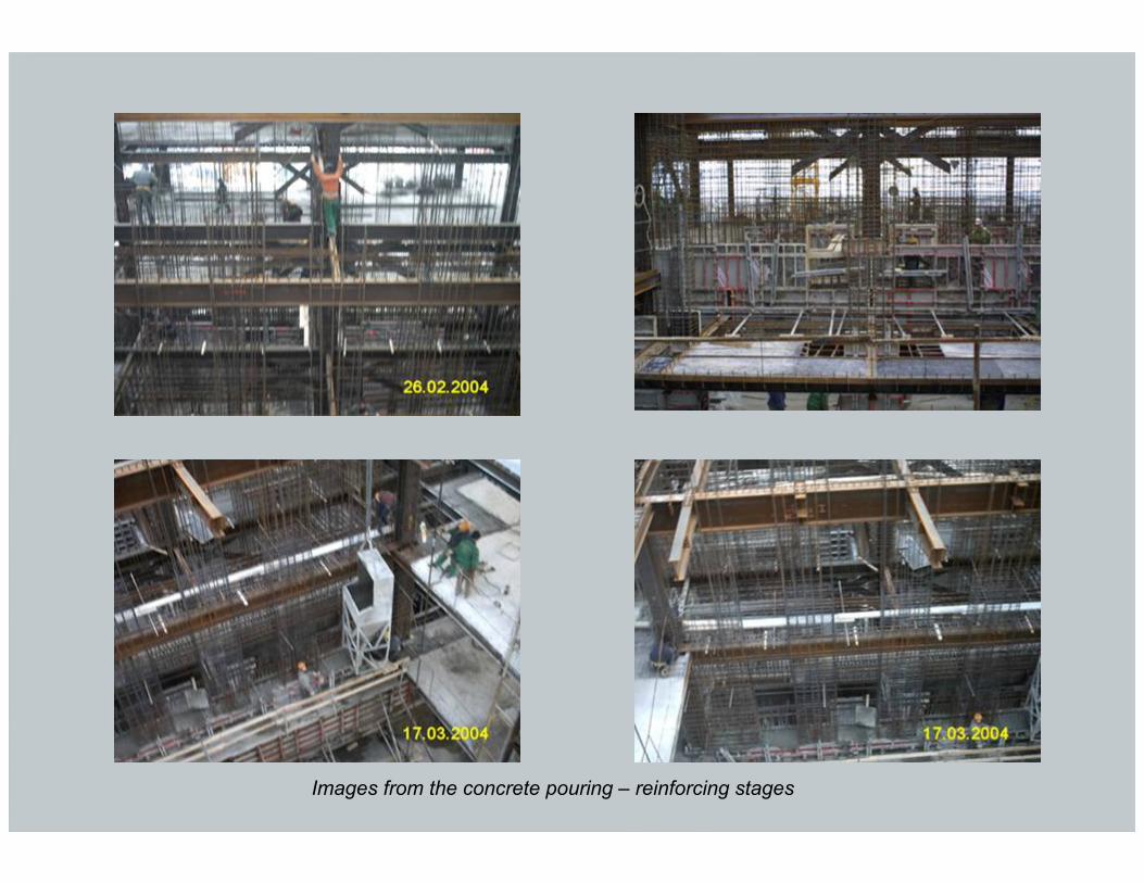
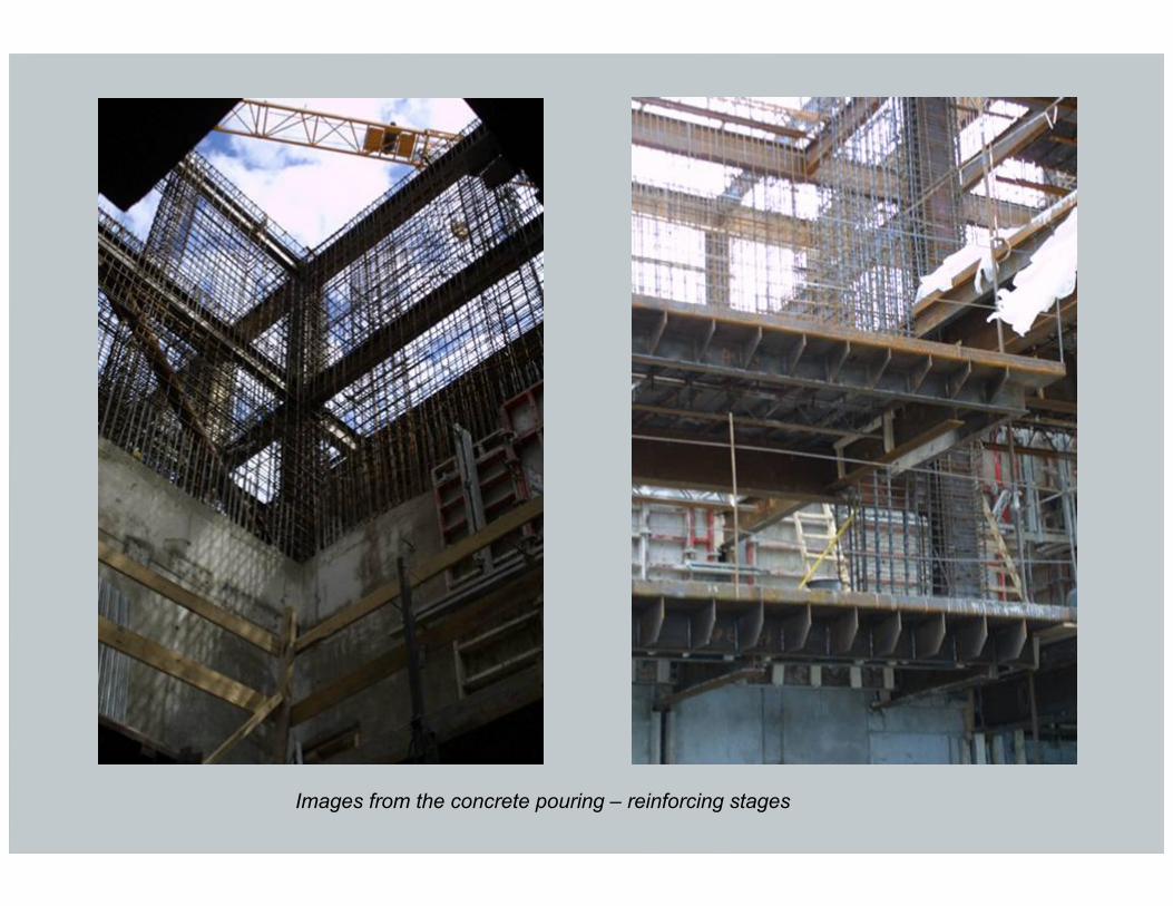
Images from the concrete pouring – reinforcing stages
Images from the concrete pouring – reinforcing stages
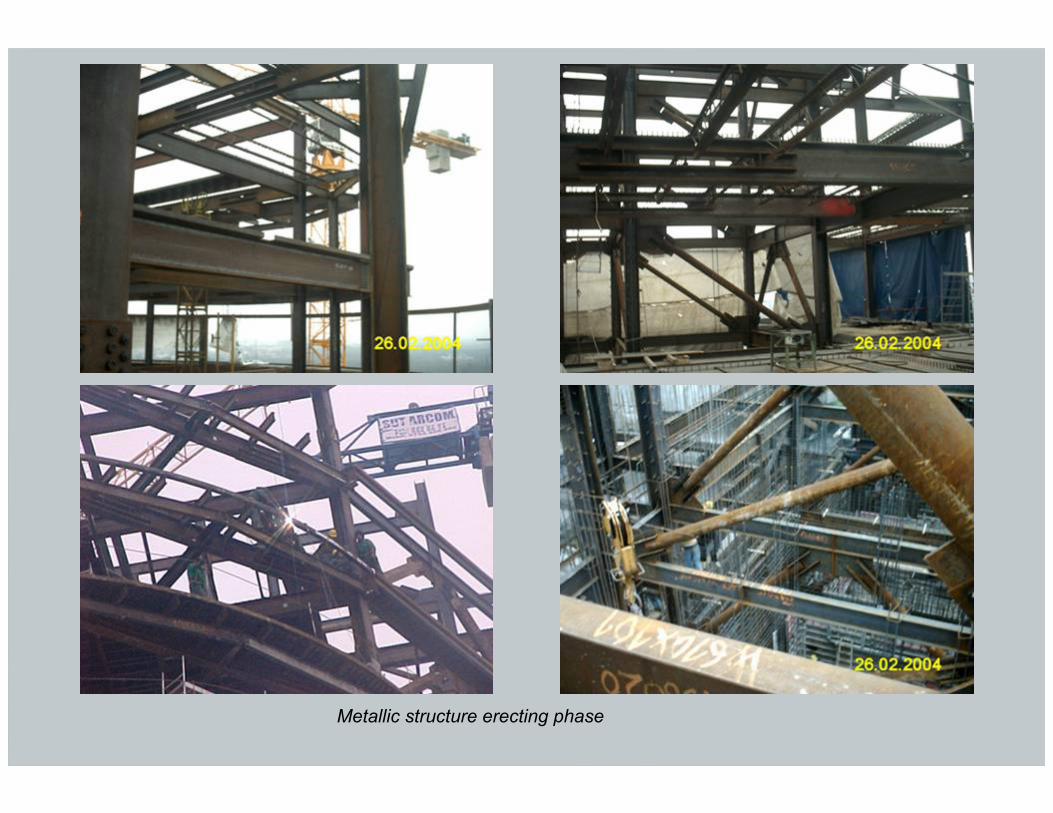
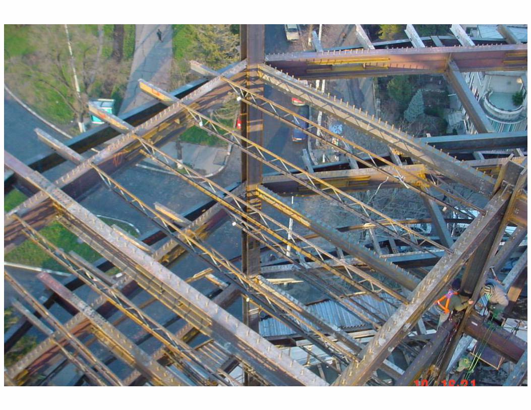
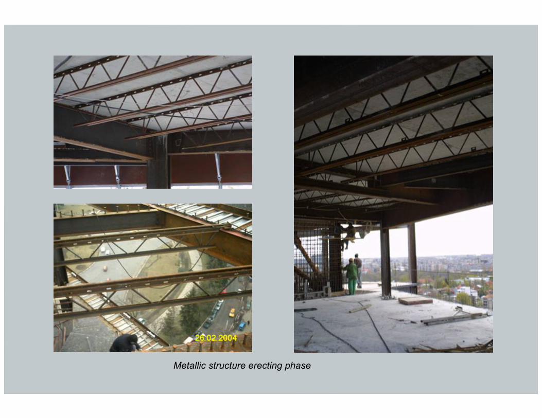
Metallic structure erecting phase
Metallic structure erecting phase
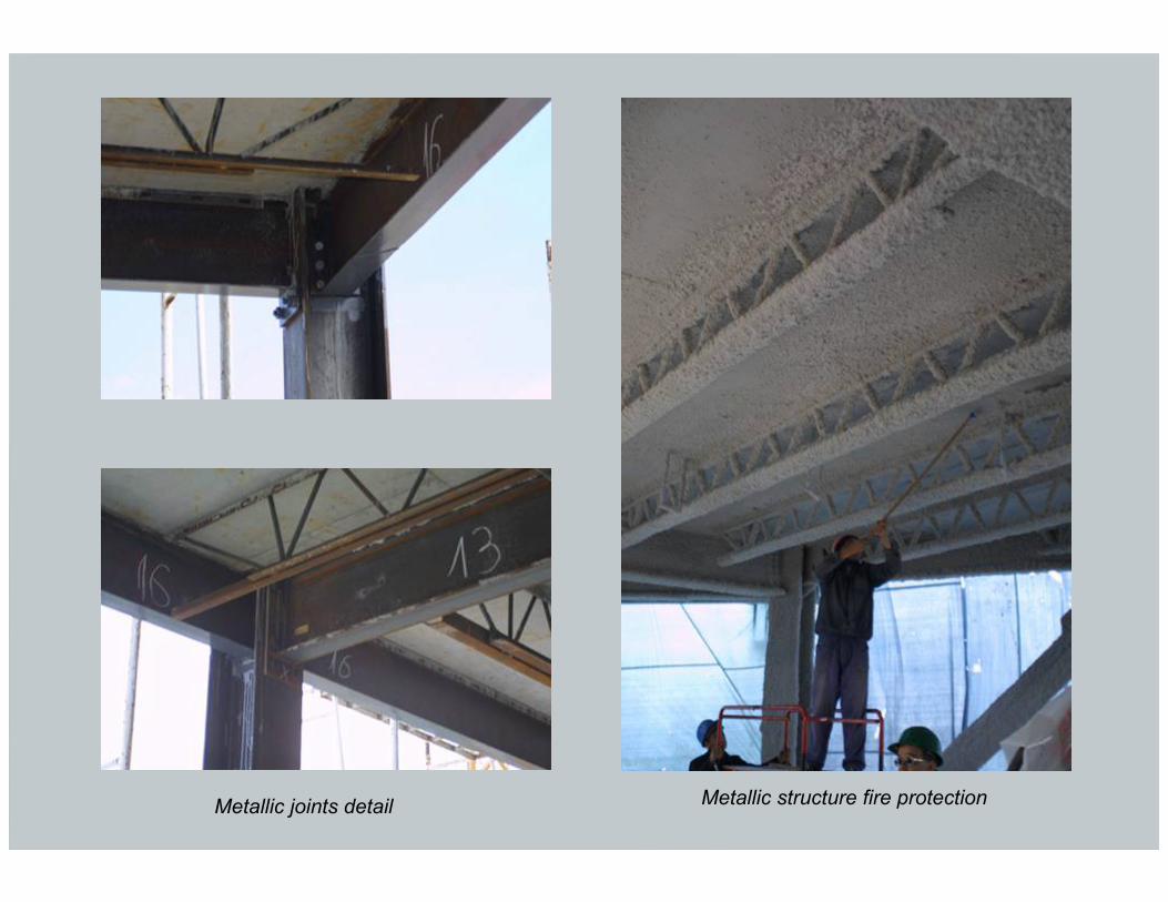
Metallic joints detail Metallic structure fire protection
OFFICE BUILDING,CHARLES DE GAULLE PLAZABucharest, Romania


