
Verilog Tutorial
Chao-Hsien, Hsu
Computer Architecture
Date: 2011/4/12
Outline
• Verilog & Example
• Major Data Type
• Operators
• Conditional & Looping Statements• Conditional & Looping Statements
• Behavior Modeling
• Structure Modeling
• Verification Methodology
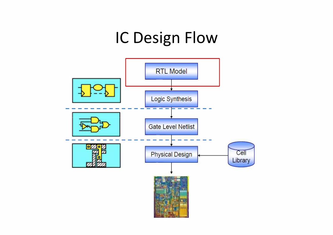
IC Design Flow
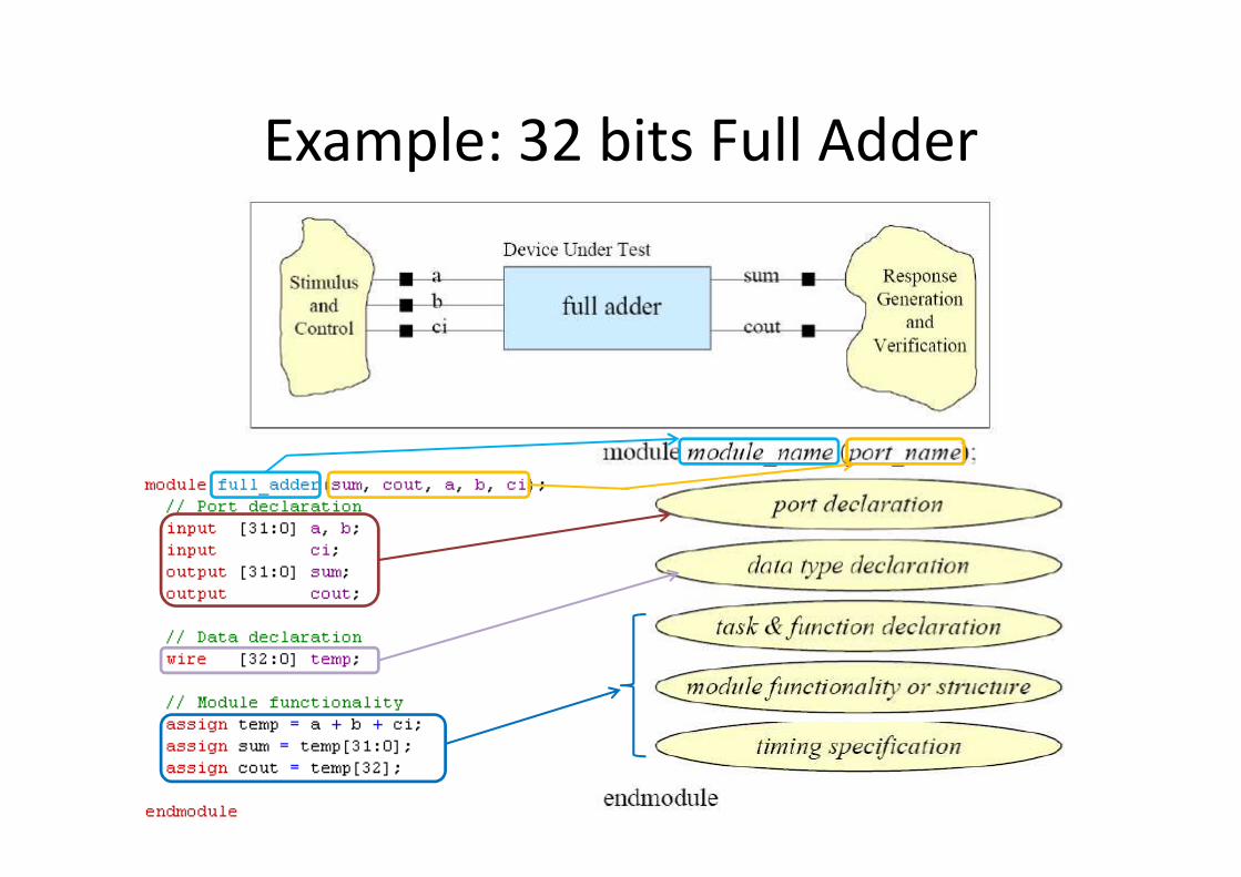
Example: 32 bits Full Adder
Outline
• Verilog & Example
• Major Data Type
• Operators
• Conditional & Looping Statements• Conditional & Looping Statements
• Behavior Modeling
• Structure Modeling
• Verification Methodology
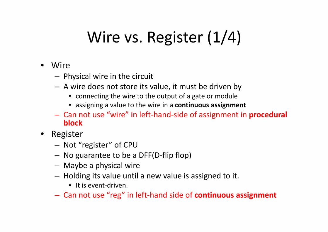
Wire vs. Register (1/4)
• Wire– Physical wire in the circuit
– A wire does not store its value, it must be driven by• connecting the wire to the output of a gate or module
• assigning a value to the wire in a continuous assignment
– Can not use “wire” in left-hand-side of assignment in procedural – Can not use “wire” in left-hand-side of assignment in procedural block
• Register– Not “register” of CPU
– No guarantee to be a DFF(D-flip flop)
– Maybe a physical wire
– Holding its value until a new value is assigned to it.• It is event-driven.
– Can not use “reg” in left-hand side of continuous assignment
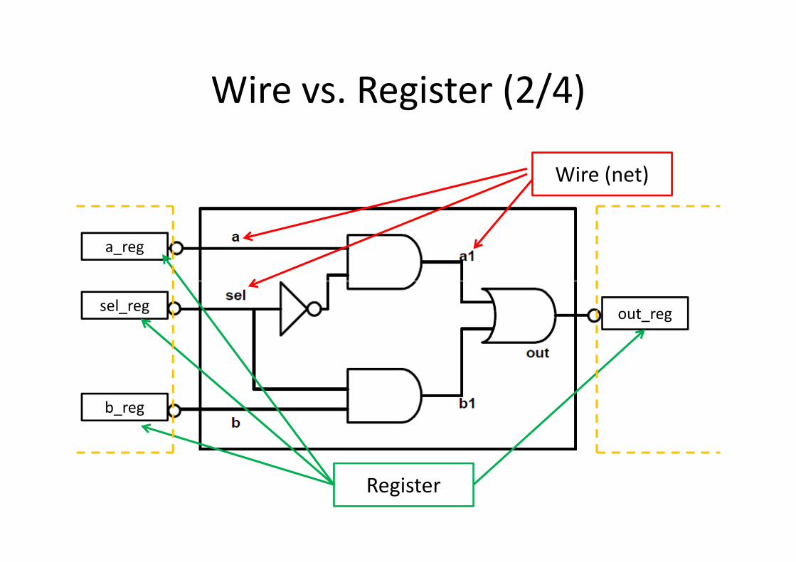
Wire vs. Register (2/4)
Wire (net)
a_reg
out_regsel_reg
b_reg
Register
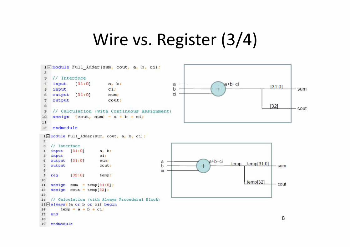
Wire vs. Register (3/4)
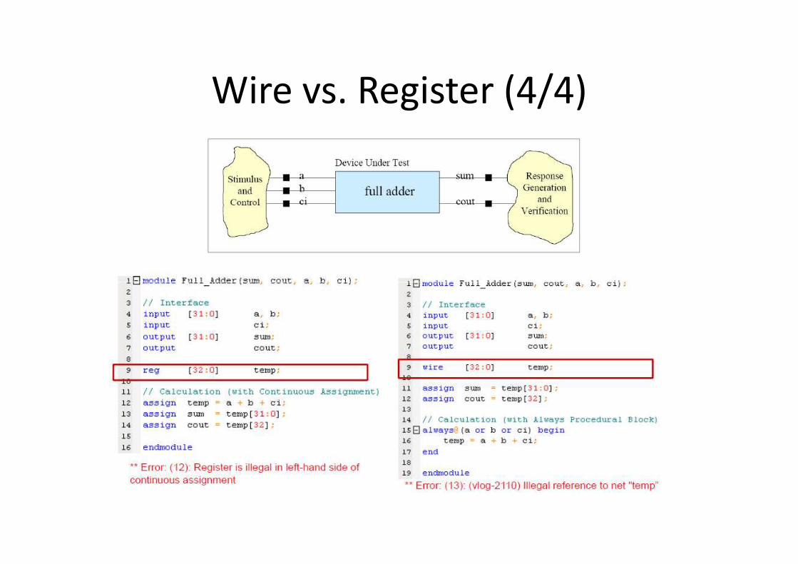
Wire vs. Register (4/4)
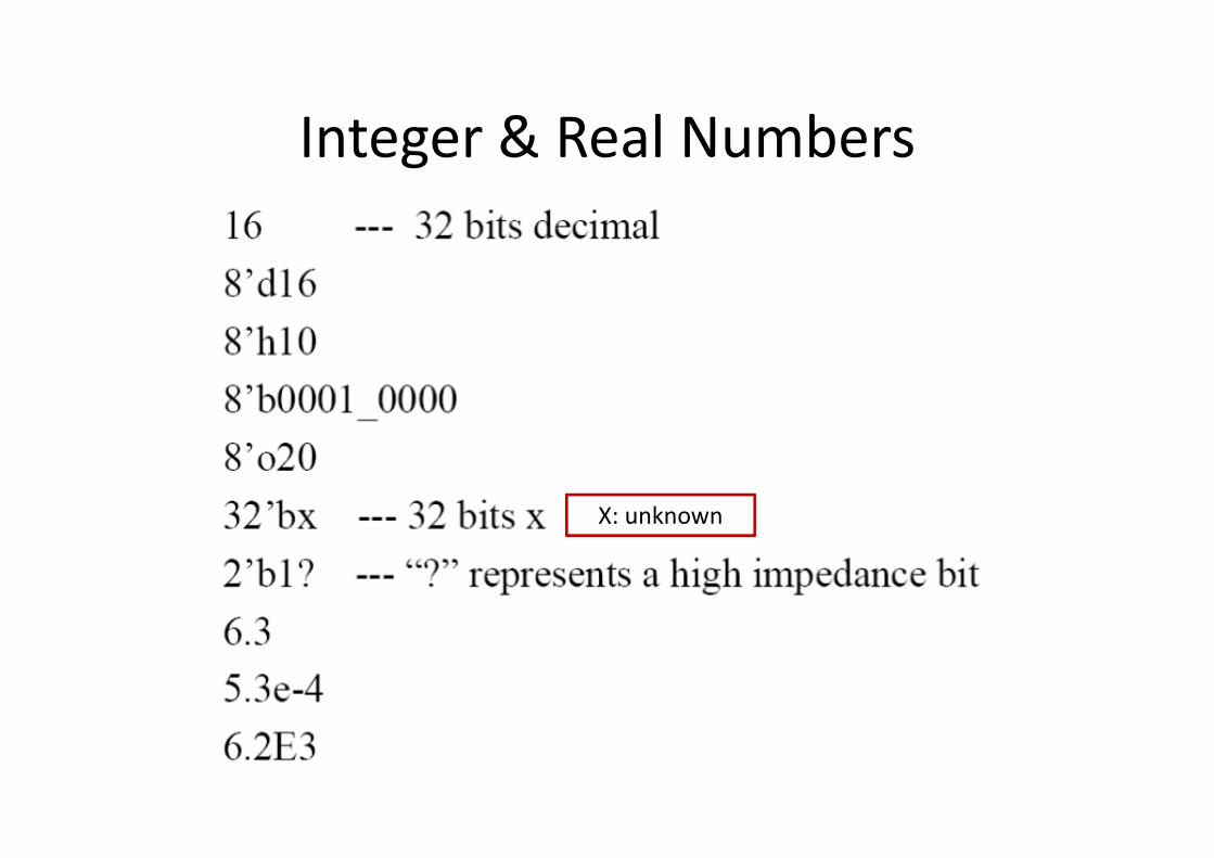
Integer & Real Numbers
X: unknown
Outline
• Verilog & Example
• Major Data Type
• Operators
• Conditional & Looping Statements• Conditional & Looping Statements
• Behavior Modeling
• Structure Modeling
• Verification Methodology
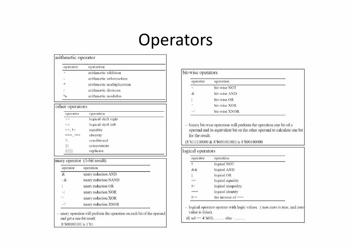
Operators
Operators: Example
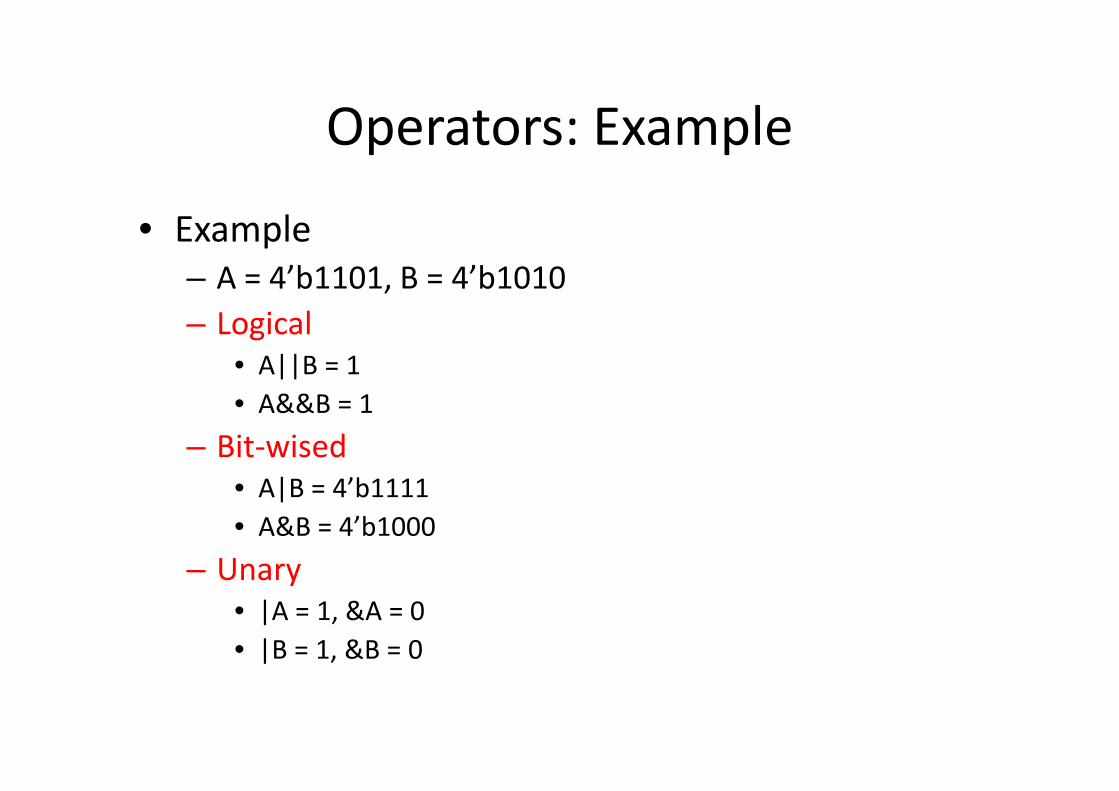
• Example
– A = 4’b1101, B = 4’b1010
– Logical
• A||B = 1
• A&&B = 1• A&&B = 1
– Bit-wised
• A|B = 4’b1111
• A&B = 4’b1000
– Unary
• |A = 1, &A = 0
• |B = 1, &B = 0
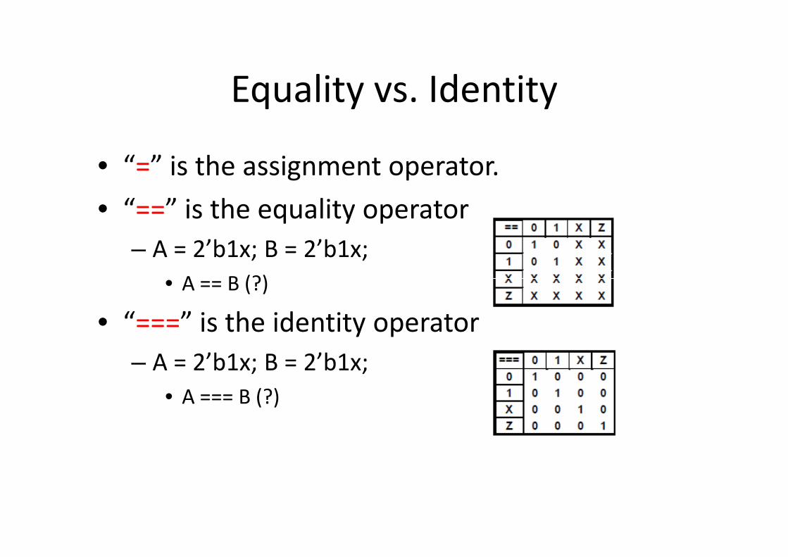
Equality vs. Identity
• “=” is the assignment operator.
• “==” is the equality operator
– A = 2’b1x; B = 2’b1x;
• A == B (?)• A == B (?)
• “===” is the identity operator
– A = 2’b1x; B = 2’b1x;
• A === B (?)
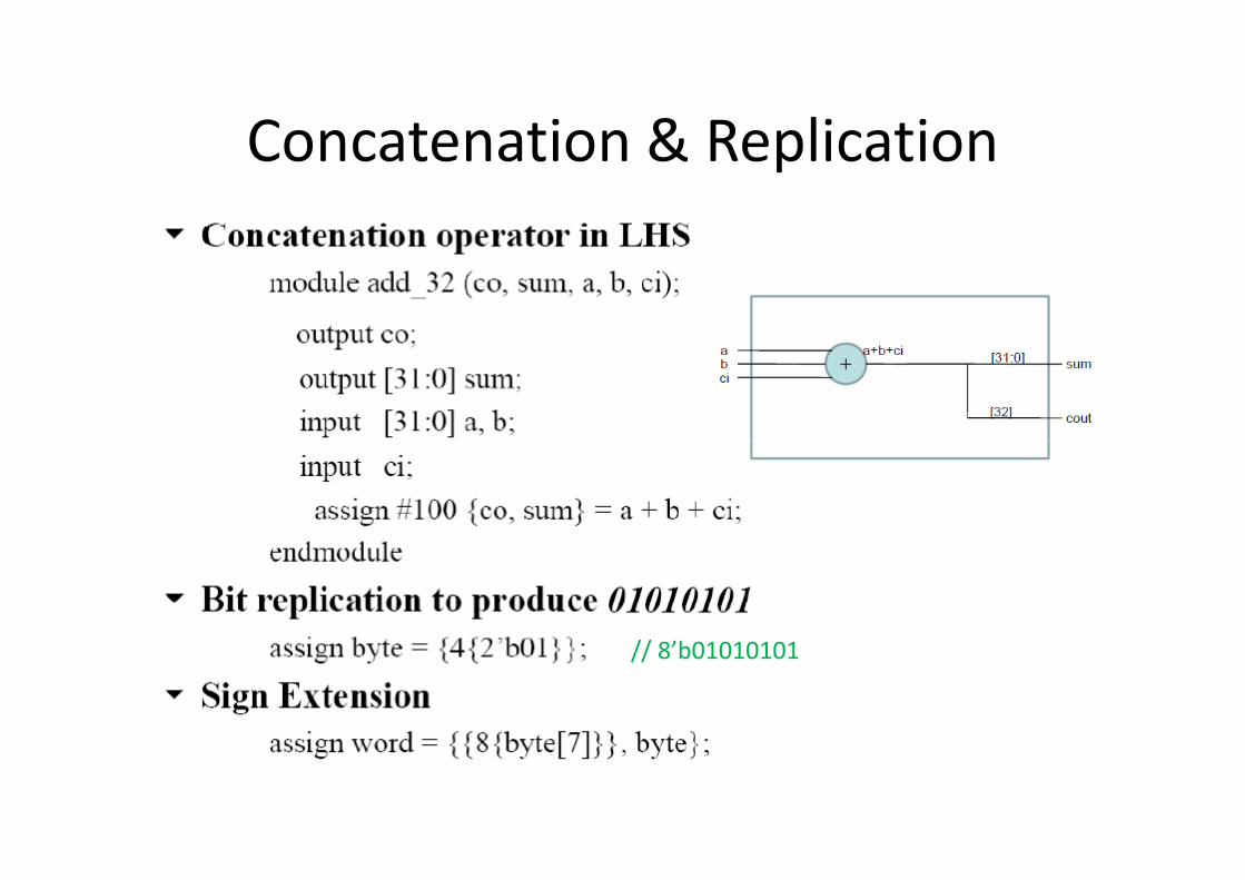
Concatenation & Replication
// 8’b01010101
Outline
• Verilog & Example
• Major Data Type
• Operators
• Conditional & Looping Statements• Conditional & Looping Statements
• Behavior Modeling
• Structure Modeling
• Verification Methodology
Behavior Model (1/3)
• At system level, system’s function view is more important than implementation.
– You do not have any idea about how to implement your net-list.
– The data flow of this system is analyzed.– The data flow of this system is analyzed.
– You may need to explore different design options.
• Behavior modeling enables you to describe the system at a high-level of abstraction.
• All you need to do is to describe the behavior of your design.
Behavior Model (2/3)
• Describing the behavior of your design(circuits).
– Action
• How do you model your circuit’s behaviors?
– Timing control– Timing control
• What time to do what thing
• What condition to do what thing
– You may need to explore different design options.
• Behavior modeling enables you to describe the
system at a high-level of abstraction.
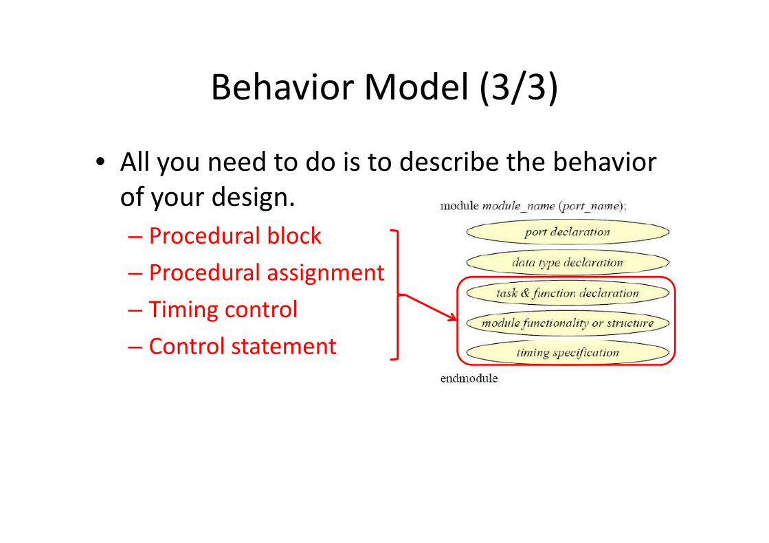
Behavior Model (3/3)
• All you need to do is to describe the behavior
of your design.
– Procedural block
– Procedural assignment– Procedural assignment
– Timing control
– Control statement
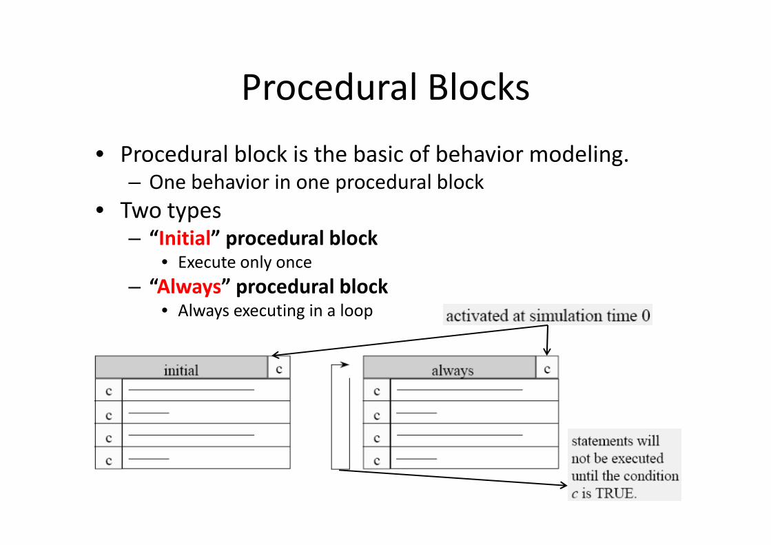
Procedural Blocks
• Procedural block is the basic of behavior modeling.– One behavior in one procedural block
• Two types– “Initial” procedural block
• Execute only once
“Always” procedural block
Execute only once
– “Always” procedural block• Always executing in a loop
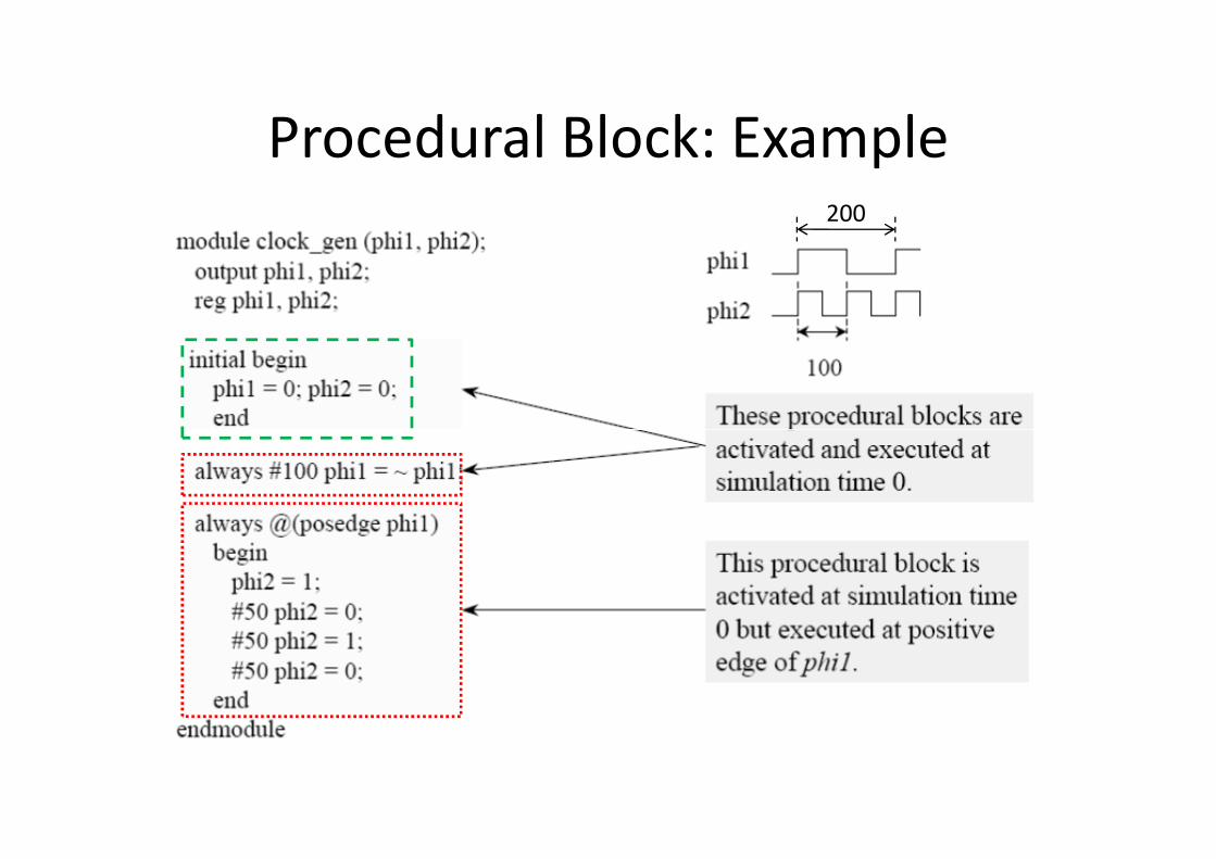
Procedural Block: Example200
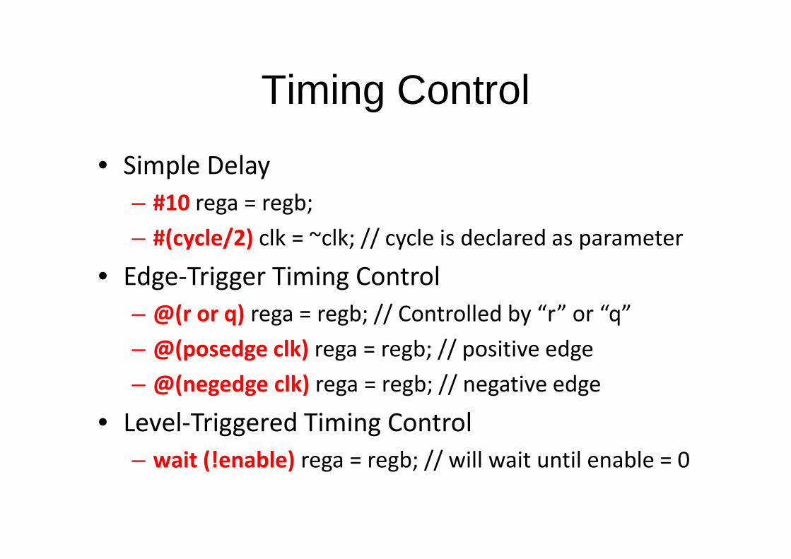
Timing Control
• Simple Delay
– #10 rega = regb;
– #(cycle/2) clk = ~clk; // cycle is declared as parameter
• Edge-Trigger Timing Control• Edge-Trigger Timing Control
– @(r or q) rega = regb; // Controlled by “r” or “q”
– @(posedge clk) rega = regb; // positive edge
– @(negedge clk) rega = regb; // negative edge
• Level-Triggered Timing Control
– wait (!enable) rega = regb; // will wait until enable = 0
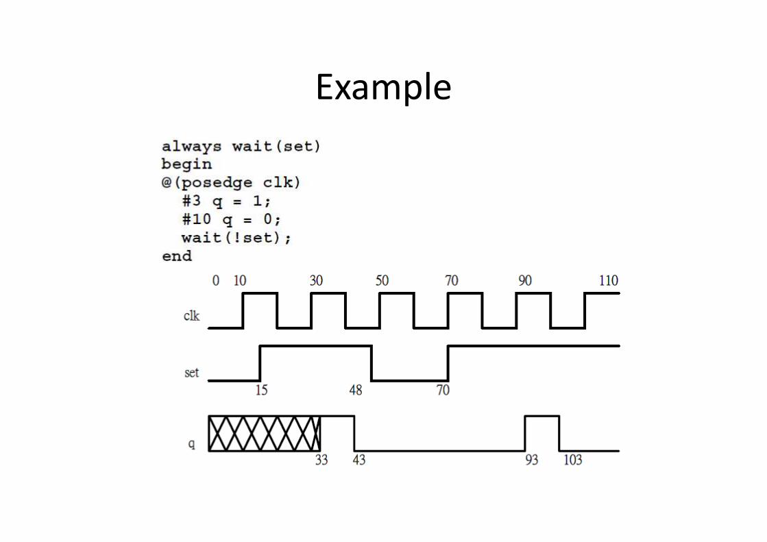
Example
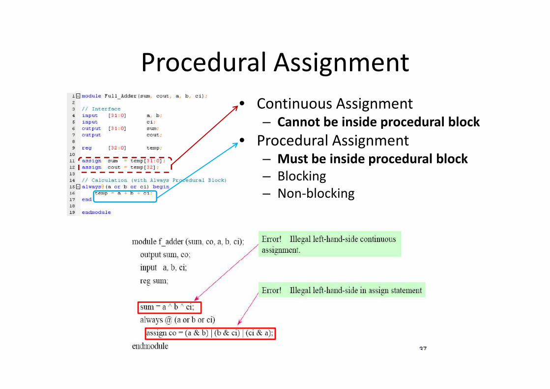
Procedural Assignment
• Continuous Assignment– Cannot be inside procedural block
• Procedural Assignment– Must be inside procedural block
– Blocking
– Non-blocking– Non-blocking
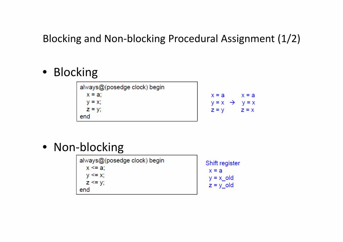
Blocking and Non-blocking Procedural Assignment (1/2)
• Blocking
• Non-blocking
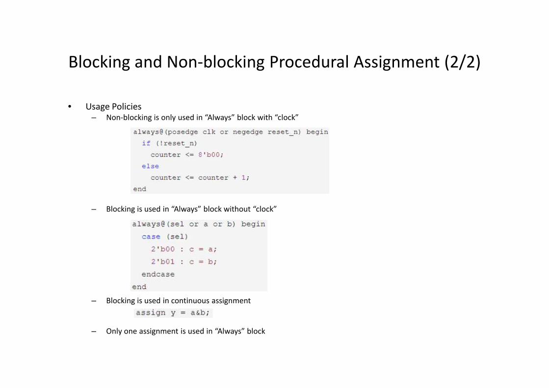
Blocking and Non-blocking Procedural Assignment (2/2)
• Usage Policies– Non-blocking is only used in “Always” block with “clock”
– Blocking is used in “Always” block without “clock”
– Blocking is used in continuous assignment
– Only one assignment is used in “Always” block
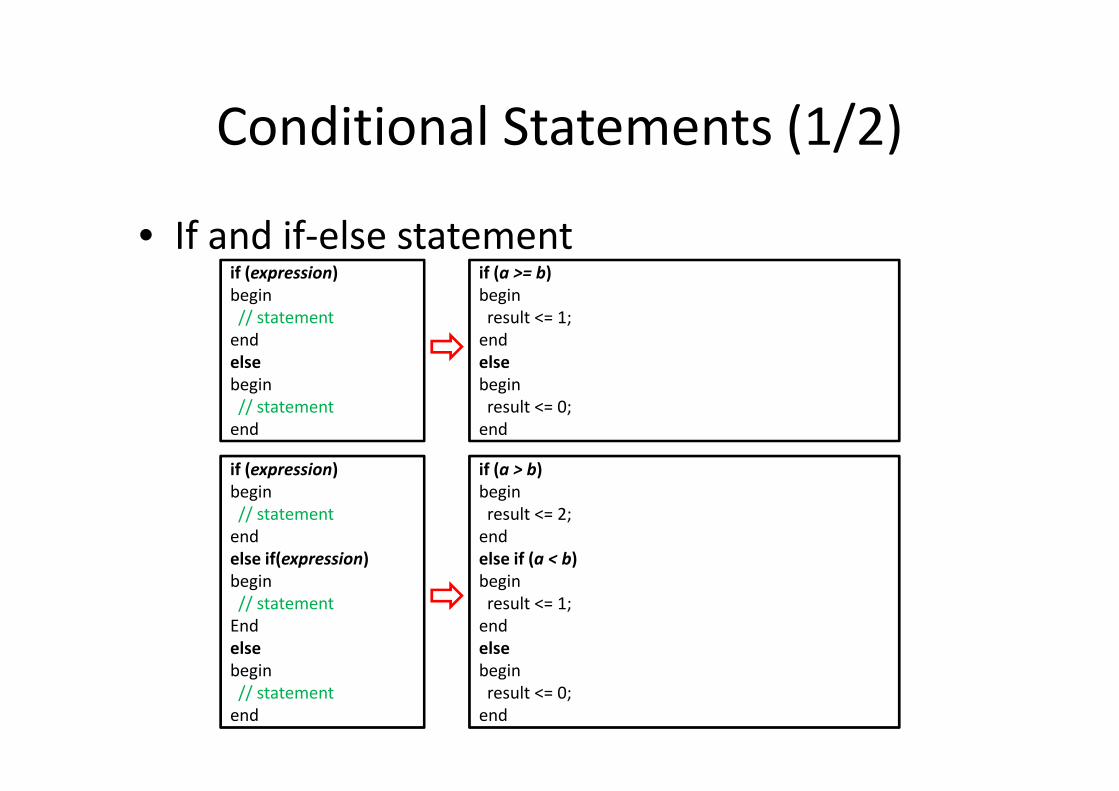
Conditional Statements (1/2)
• If and if-else statementif (expression)
begin
// statement
end
else
begin
// statement
if (a >= b)
begin
result <= 1;
end
else
begin
result <= 0;// statement
end
if (expression)
begin
// statement
end
else if(expression)
begin
// statement
End
else
begin
// statement
end
result <= 0;
end
if (a > b)
begin
result <= 2;
end
else if (a < b)
begin
result <= 1;
end
else
begin
result <= 0;
end
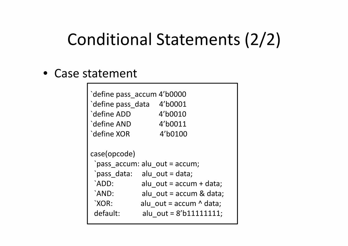
Conditional Statements (2/2)
• Case statement
`define pass_accum 4’b0000
`define pass_data 4’b0001
`define ADD 4’b0010
`define AND 4’b0011`define AND 4’b0011
`define XOR 4’b0100
case(opcode)
`pass_accum: alu_out = accum;
`pass_data: alu_out = data;
`ADD: alu_out = accum + data;
`AND: alu_out = accum & data;
`XOR: alu_out = accum ^ data;
default: alu_out = 8’b11111111;
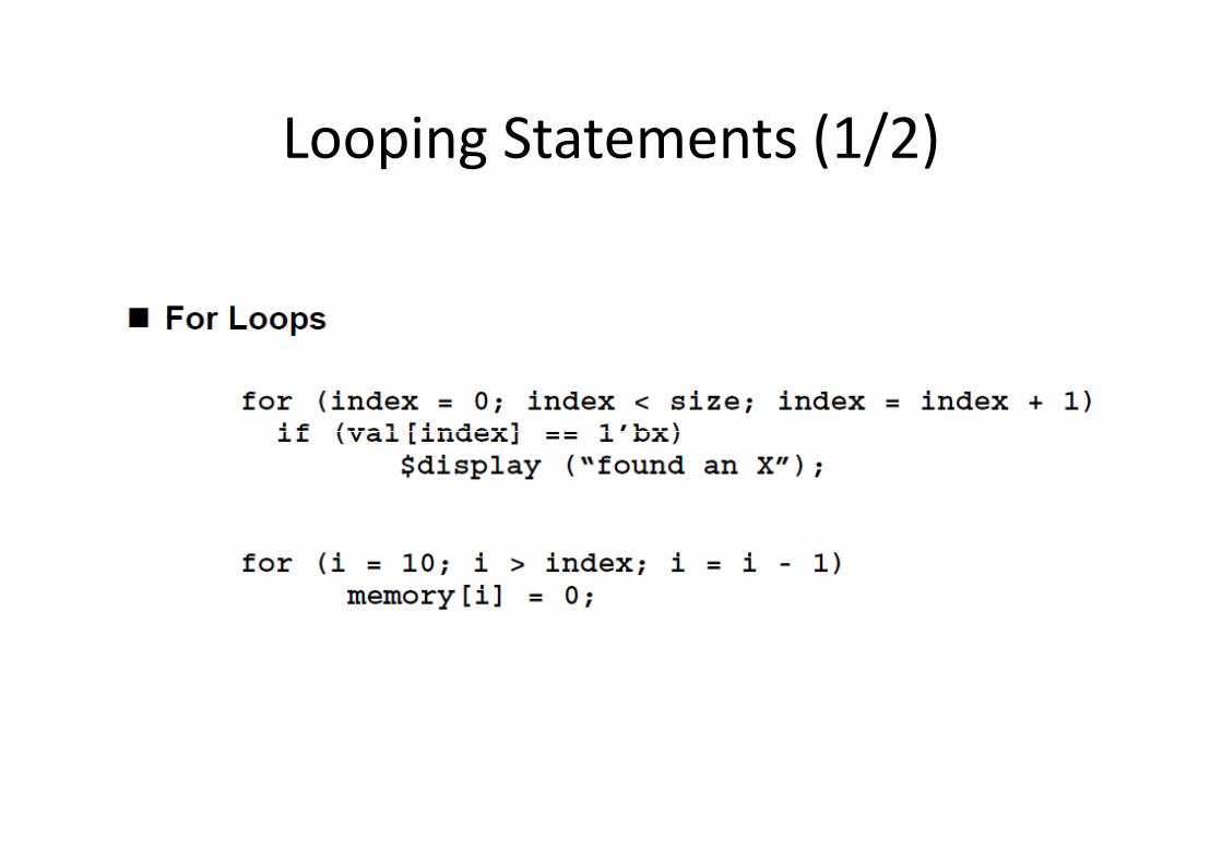
Looping Statements (1/2)
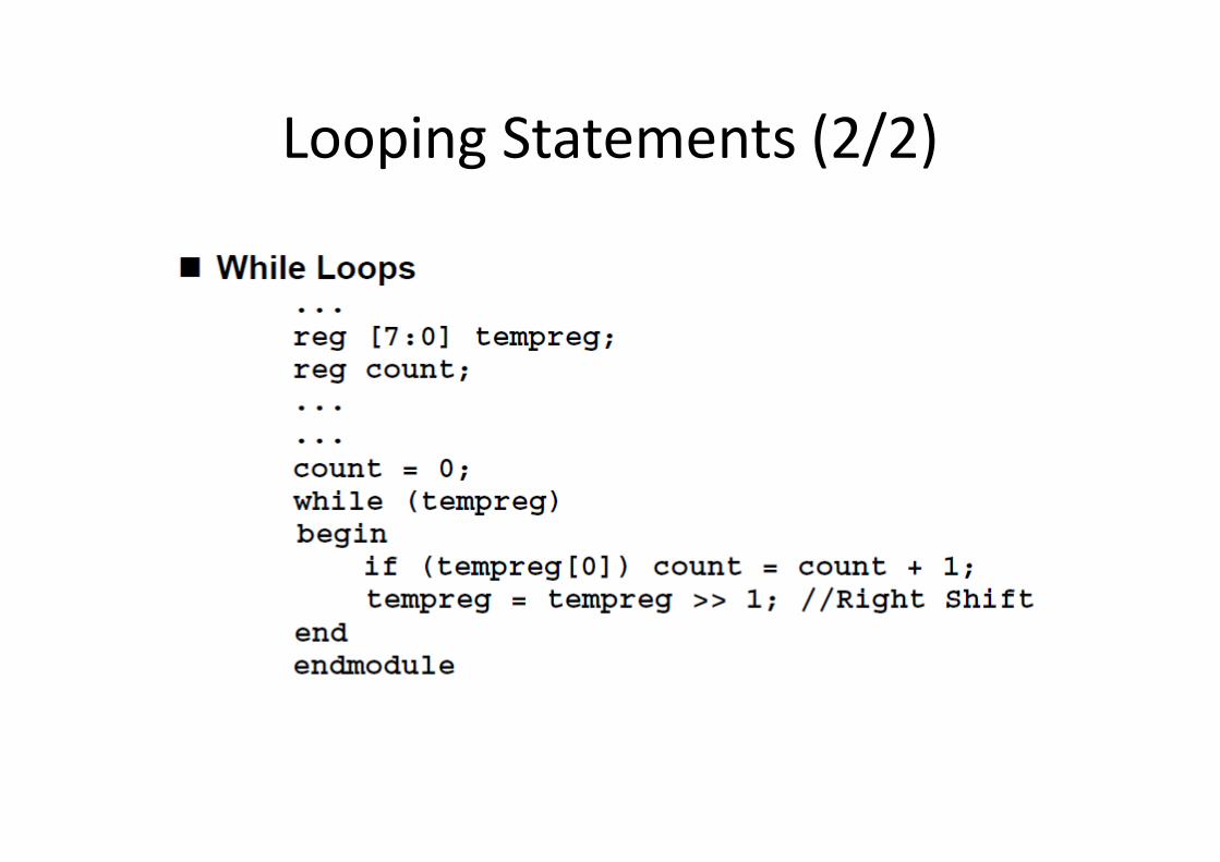
Looping Statements (2/2)
Outline
• Verilog & Example
• Major Data Type
• Operators
• Conditional & Looping Statements• Conditional & Looping Statements
• Behavior Modeling
• Structure Modeling
• Verification Methodology
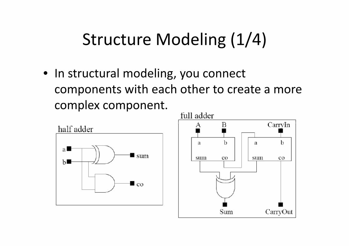
Structure Modeling (1/4)
• In structural modeling, you connect
components with each other to create a more
complex component.
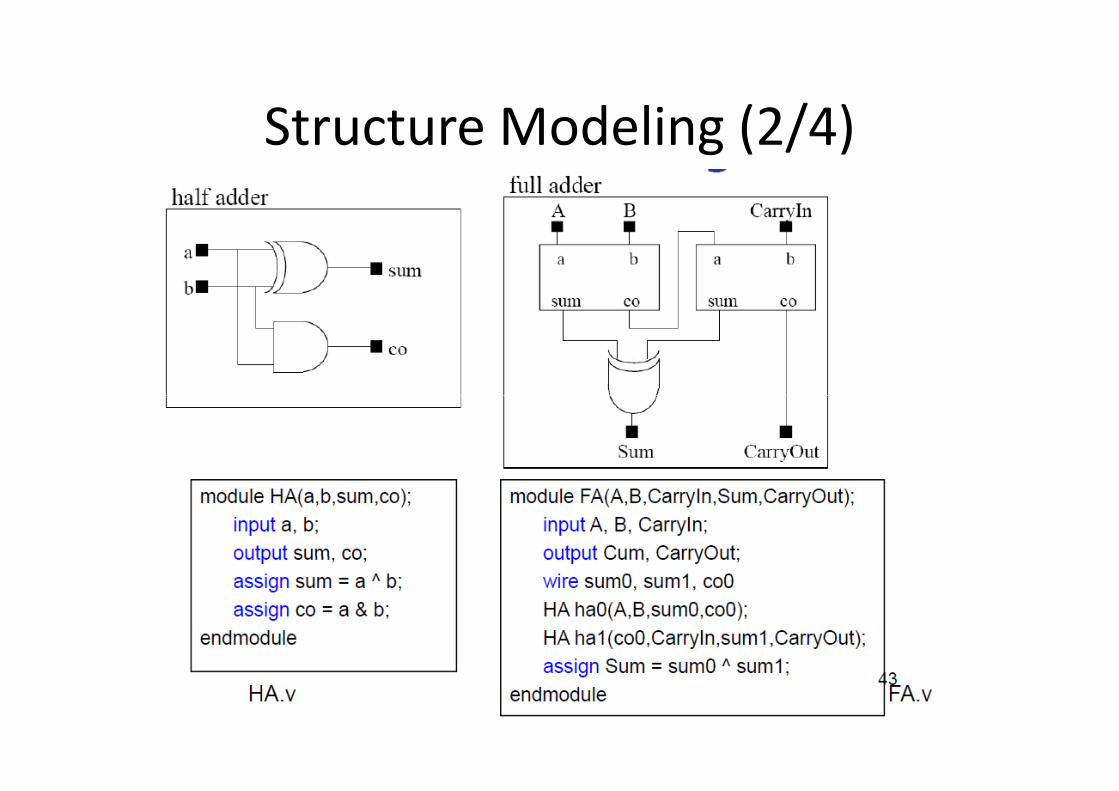
Structure Modeling (2/4)
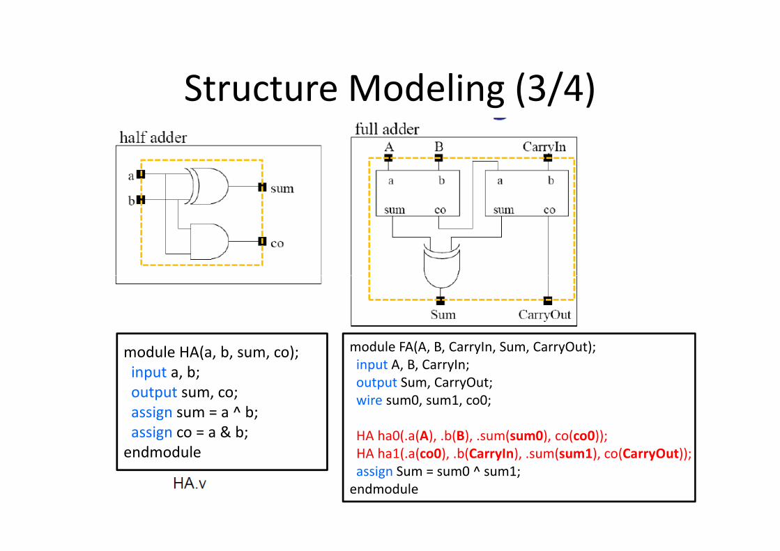
Structure Modeling (3/4)
module HA(a, b, sum, co);
input a, b;
output sum, co;
assign sum = a ^ b;
assign co = a & b;
endmodule
module FA(A, B, CarryIn, Sum, CarryOut);
input A, B, CarryIn;
output Sum, CarryOut;
wire sum0, sum1, co0;
HA ha0(.a(A), .b(B), .sum(sum0), co(co0));
HA ha1(.a(co0), .b(CarryIn), .sum(sum1), co(CarryOut));
assign Sum = sum0 ^ sum1;
endmodule
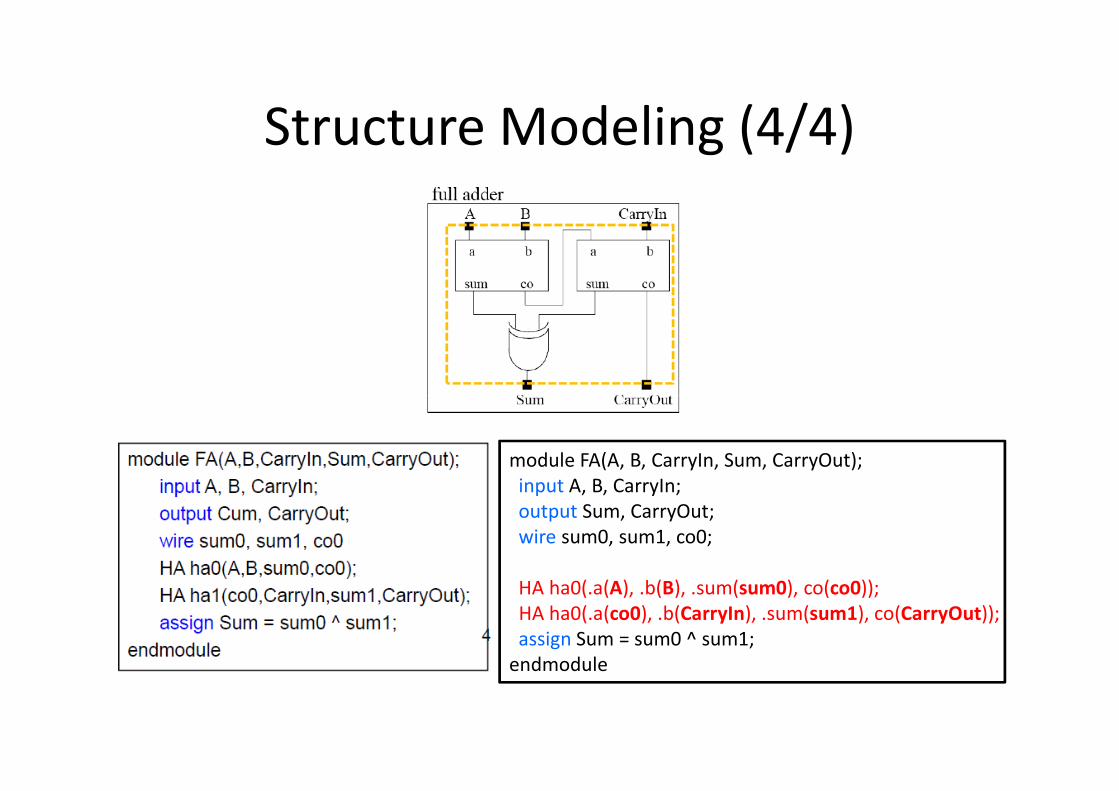
Structure Modeling (4/4)
module FA(A, B, CarryIn, Sum, CarryOut);
input A, B, CarryIn;
output Sum, CarryOut;
wire sum0, sum1, co0;
HA ha0(.a(A), .b(B), .sum(sum0), co(co0));
HA ha0(.a(co0), .b(CarryIn), .sum(sum1), co(CarryOut));
assign Sum = sum0 ^ sum1;
endmodule
Outline
• Verilog & Example
• Major Data Type
• Operators
• Conditional & Looping Statements• Conditional & Looping Statements
• Behavior Modeling
• Structure Modeling
• Verification Methodology
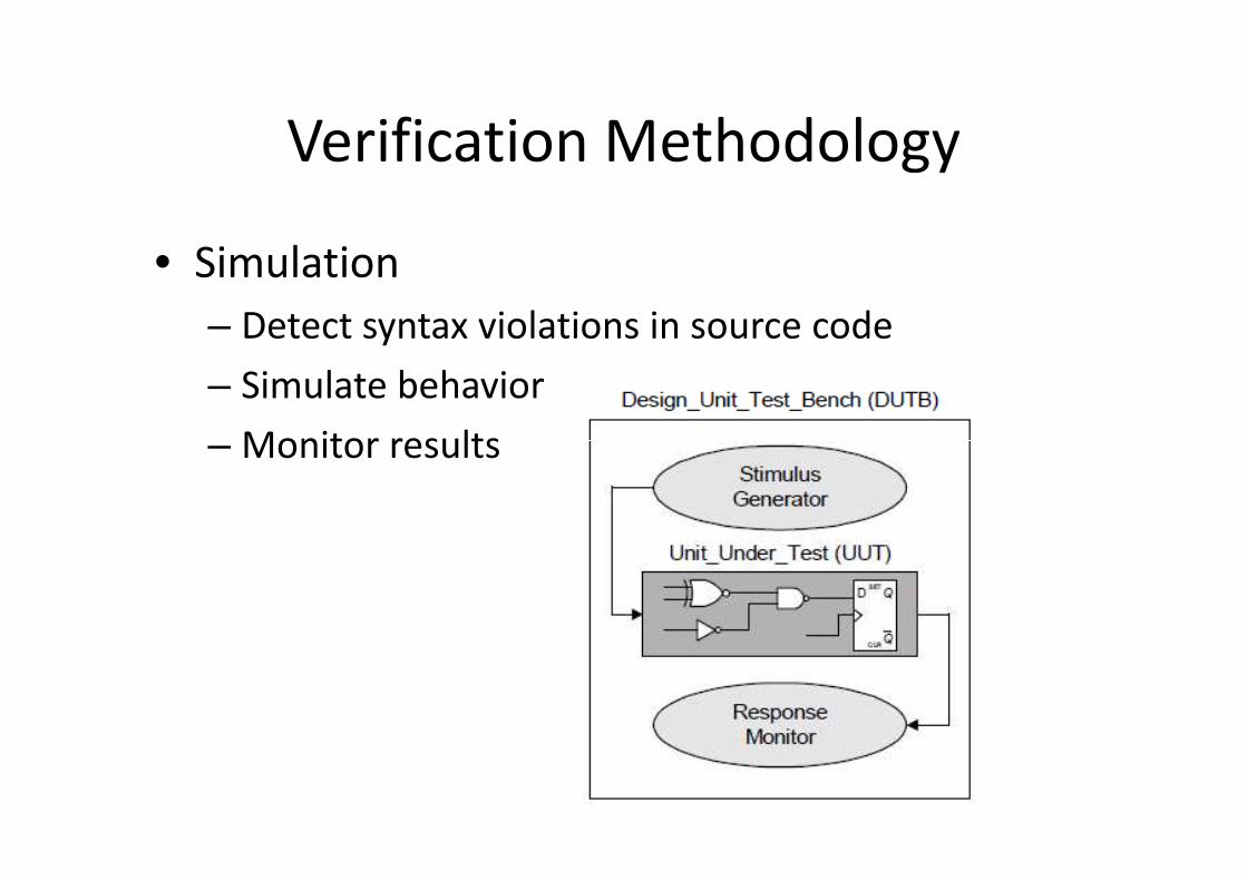
Verification Methodology
• Simulation
– Detect syntax violations in source code
– Simulate behavior
– Monitor results– Monitor results
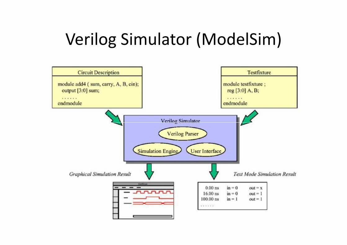
Verilog Simulator (ModelSim)
VHDL & Verilog
• Process Block
• Signal Assignment
• Interface Declaration
• Buses• Buses
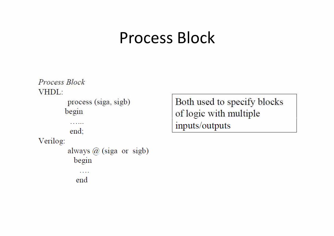
Process Block
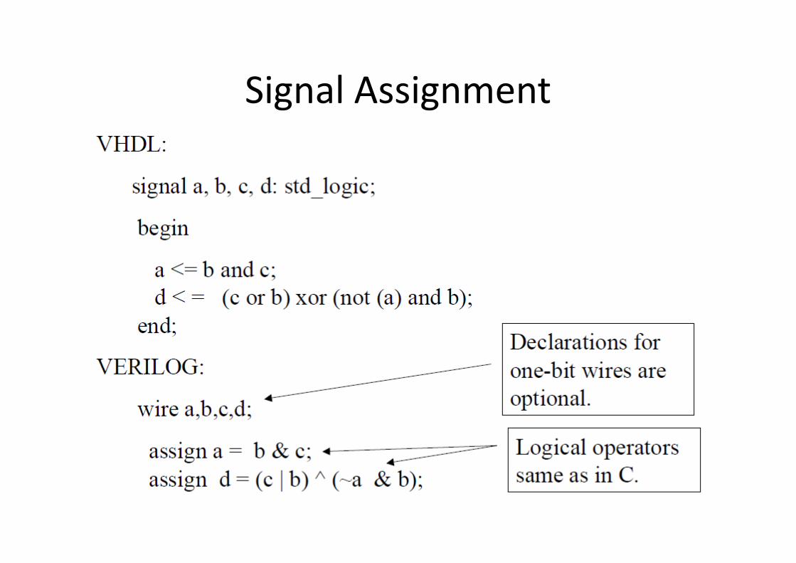
Signal Assignment
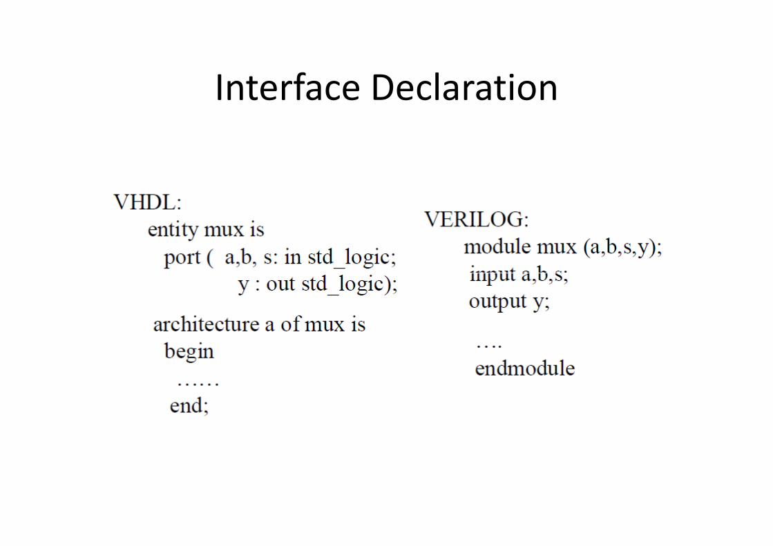
Interface Declaration
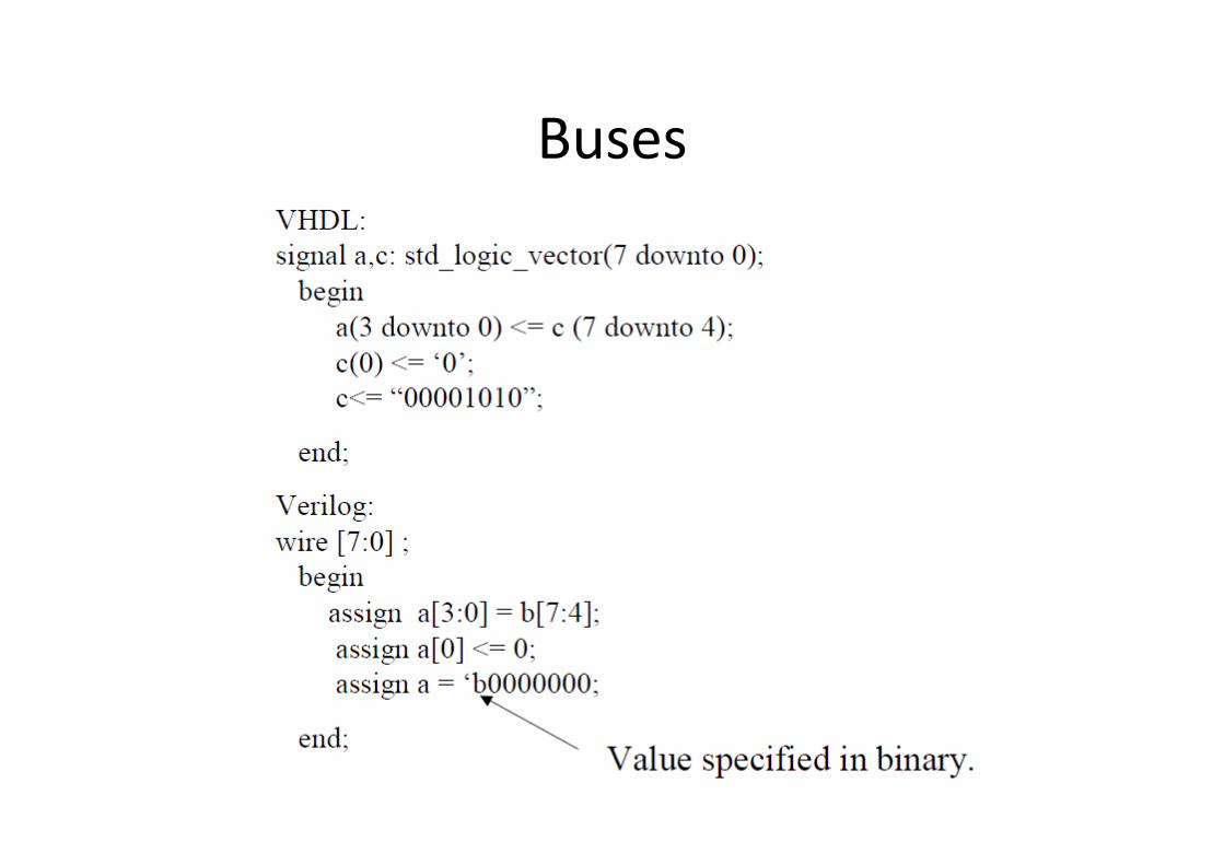
Buses
Reference
• Some contents are referenced from the below
materials
– The slides of the “VLSI System Design” course by
Prof. Kuen-Jong LeeProf. Kuen-Jong Lee
– The slides of the “Digital System Design” course by
Prof. An-Yeu (Andy) Wu
– http://www.ece.msstate.edu/~reese/EE4743/lect
ures/verilog_intro_2002/verilog_intro_2002.pdf


