U.P.B. Sci. Bull., Series C, Vol. 68, No. 2, 2006 USING STEREO VISION FOR REAL-TIME HEAD-POSE AND GAZE ESTIMATION C. CUDALBU, B. ANASTASIU, H. GRECU, V. BUZULOIU ∗ Sistemele inteligente cu interacţiune umană şi sistemele de securitate bazate pe camere video necesită în multe condiţii estimarea poziţiei capului şi a direcţiei privirii. Cum mişcarea capului şi a ochilor unei persoane este stâns legată de atenţia si intenţiile persoanei, informaţiile date de poziţia capului şi direcţia privirii pot fi folosite pentru a construi o interfaţǎ cu subiectul, naturalǎ şi intuitivǎ. În acest articol propunem un algoritm robust pentru estimarea poziţiei capului şi a direcţiei privirii in timp real, folosind două camere video. Astfel coordonatele 3D ale trăsăturilor dominante ale unei feţe, pot fi măsurate folosind principiul triangulaţiei, obţinând o acurateţe semnificativ mai bună decât a sistemelor care folosesc o singură cameră video pentru estimarea poziţiei şi orientării capului. Smart human-computer interfaces and video-based security systems often require the estimation of head pose and gaze direction. Since the motion of a person's head and eyes are related to her or his intentions and attention, head-pose and gaze information can be used to build natural and intuitive interfaces. In this paper, we propose a robust algorithm for real-time head-pose and gaze estimation that uses two cameras. Such, the 3D coordinates of the features on a face can be measured by triangulation, and thus a significantly better accuracy can be obtained over vision-based systems that use a single camera for the estimation of the head position and orientation. Keywords: computer vision, real-time head tracking, real-time gaze tracking, human computer interfaces, stereo vision Introduction A new application domain in computer vision has emerged over the past few years dealing with the analysis of images involving humans. This domain (sometimes called “Looking at People”) [1] involves, among other issues, head- pose and gaze estimation. Being able to track the head position and orientation together with his or her gaze direction in a three dimensional space has become a crucial task for several computer-vision applications. Problems like face recognition, facial expression analysis, lip reading, video conferencing etc., are more likely to be solved if a stabilized image of the face is generated by a 3D tracker. Determining the 3D position and orientation of the head is also ∗ Eng., Eng., Eng., Prof., LAPI, University POLITEHNICA of Bucharest, Romania
Transcript
U.P.B. Sci. Bull., Series C, Vol. 68, No. 2, 2006
USING STEREO VISION FOR REAL-TIME HEAD-POSE AND GAZE ESTIMATION
C. CUDALBU, B. ANASTASIU, H. GRECU, V. BUZULOIU∗
Sistemele inteligente cu interacţiune umană şi sistemele de securitate bazate pe camere video necesită în multe condiţii estimarea poziţiei capului şi a direcţiei privirii. Cum mişcarea capului şi a ochilor unei persoane este stâns legată de atenţia si intenţiile persoanei, informaţiile date de poziţia capului şi direcţia privirii pot fi folosite pentru a construi o interfaţǎ cu subiectul, naturalǎ şi intuitivǎ. În acest articol propunem un algoritm robust pentru estimarea poziţiei capului şi a direcţiei privirii in timp real, folosind două camere video. Astfel coordonatele 3D ale trăsăturilor dominante ale unei feţe, pot fi măsurate folosind principiul triangulaţiei, obţinând o acurateţe semnificativ mai bună decât a sistemelor care folosesc o singură cameră video pentru estimarea poziţiei şi orientării capului.
Smart human-computer interfaces and video-based security systems often require the estimation of head pose and gaze direction. Since the motion of a person's head and eyes are related to her or his intentions and attention, head-pose and gaze information can be used to build natural and intuitive interfaces. In this paper, we propose a robust algorithm for real-time head-pose and gaze estimation that uses two cameras. Such, the 3D coordinates of the features on a face can be measured by triangulation, and thus a significantly better accuracy can be obtained over vision-based systems that use a single camera for the estimation of the head position and orientation.
Keywords: computer vision, real-time head tracking, real-time gaze tracking, human computer interfaces, stereo vision
Introduction
A new application domain in computer vision has emerged over the past few years dealing with the analysis of images involving humans. This domain (sometimes called “Looking at People”) [1] involves, among other issues, head-pose and gaze estimation. Being able to track the head position and orientation together with his or her gaze direction in a three dimensional space has become a crucial task for several computer-vision applications. Problems like face recognition, facial expression analysis, lip reading, video conferencing etc., are more likely to be solved if a stabilized image of the face is generated by a 3D tracker. Determining the 3D position and orientation of the head is also ∗ Eng., Eng., Eng., Prof., LAPI, University POLITEHNICA of Bucharest, Romania
C. Cudalbu, B. Anastasiu, H. Grecu, V. Buzuloiu 16
fundamental in the development of future vision-driven user interfaces and, more generally for head gesture recognition. With the continuously increasing computational power of a mid-range workstation, a head pose and gaze estimation system can be developed without fear of computational explosion limitations.
Several systems exist to determine a person’s head position and orientation but some use magnetic sensors [2] or mechanical links and those that use stereo vision require extensive manual initialization [3]. The approach that we use has the advantage over the previously mentioned systems of being fully automatic for the determination of head pose and requiring minimal calibration for gaze estimation. The system is also non-contact, compact and accurate.
1. Problem Statement
The aim of our system is to determine the head pose (Δpitch, Δyaw, Δroll, Δx, Δy, Δz) of a human head together with the gaze direction using stereo vision. The hypothesis is that the head rotates around the y-axis with maximum 90 degrees, around x-axis with maximum 45 degrees and around z-axis with maximum 45 degrees, and that the head-space volume ranges roughly from 450 and 900 mm in depth.
The head is viewed as a rigid body so the false motions indications due to speech or facial expressions are only partially compensated for at this moment. In the current implementation we use a random sample consensus (RANSAC) [4] algorithm to eliminate those features that are non-rigid. This approach works properly if most of the features are tracked, such as to have a large base for feature selection.
2. The Algorithm
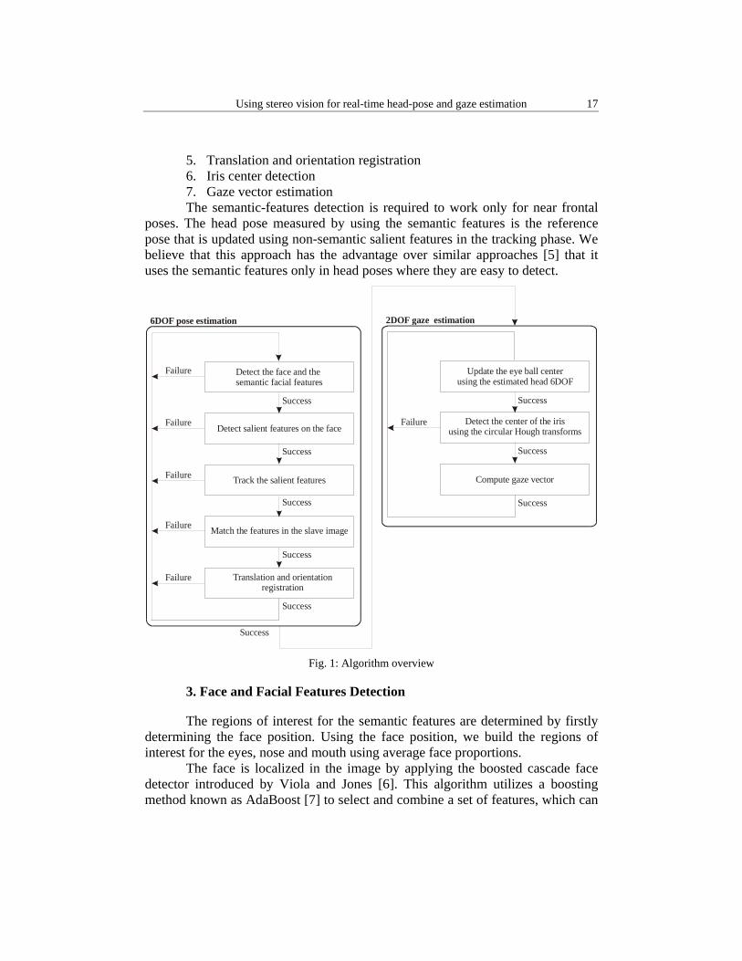
The outline of the software configuration of our algorithm is shown in Fig. 1. For initialization, the system needs to locate the position of the facial features in the master camera. These features are later matched in the slave camera to recover the initial 3D position. Once they are detected, salient non-semantic facial features are selected. Using these features the 3D position and orientation of the head are computed. With the circular Hough transform the 2D center of the irises is detected. The 3D relative position of the eyeball center respect to the head model is detected in a calibration procedure. The gaze vector is computed using the center of the iris and eye ball center.
The algorithm has several modules: 1. Face and facial features detection 2. Salient facial features detection 3. Tracking both sets of features 4. 3D reconstruction
Using stereo vision for real-time head-pose and gaze estimation 17
5. Translation and orientation registration 6. Iris center detection 7. Gaze vector estimation The semantic-features detection is required to work only for near frontal
poses. The head pose measured by using the semantic features is the reference pose that is updated using non-semantic salient features in the tracking phase. We believe that this approach has the advantage over similar approaches [5] that it uses the semantic features only in head poses where they are easy to detect.
Detect the face and the semantic facial features
Detect salient features on the face
Track the salient features
Match the features in the slave image
Translation and orientation registration
Success
Success
Success
Success
Success
Failure
Failure
Failure
Failure
Failure
6DOF pose estimation
Update the eye ball centerusing the estimated head 6DOF
Compute gaze vector
Success
Success
Success
Failure
2DOF gaze estimation
Detect the center of the iris using the circular Hough transforms
Success
Fig. 1: Algorithm overview
3. Face and Facial Features Detection
The regions of interest for the semantic features are determined by firstly determining the face position. Using the face position, we build the regions of interest for the eyes, nose and mouth using average face proportions.
The face is localized in the image by applying the boosted cascade face detector introduced by Viola and Jones [6]. This algorithm utilizes a boosting method known as AdaBoost [7] to select and combine a set of features, which can
C. Cudalbu, B. Anastasiu, H. Grecu, V. Buzuloiu 18
discriminate between face and non-face image regions. The detector is run over a test image and the image window with the highest face score is deemed to be the location of the face in the image.
Facial-features detectors are built for 8 features: the four inner and outer eye corners, the two nostrils and the two mouth corners. For each feature we create a training set consisting of roughly 300 positive samples and 1000 negative samples. The training set is used to train a boosted cascade detector for each individual feature.
Given the regions computed by the face detector, feature detection proceeds by searching within the regions and the best match is taken as the location of each feature.
The semantic-features detection succeeds if it finds at least 2 of the 4 eye corners from either eye and at least one mouth corner. The face normal is computed as the average of the normal of each of the planes formed by the eye corners and the mouth. A 3D shape constraint is used to check the configuration of the detected features. Not having the face within our typical predefined range is considered a failure and the process is restarted.
4. Salient Feature Detection
To increase the robustness of our system, we also compute non-semantic salient features. This is necessary because the semantic features may become occluded due to head motion. There is one important requirement for the salient facial-feature points. There should be sufficient information in the neighborhood of the points such that corresponding points can be easily matched in the slave image. In our system the Harris corner detector [8] is used to find salient non-semantic features. Our decision is sustain by the fact that corners are stable across image sequences and are useful in image matching for stereo and object tracking for motion.
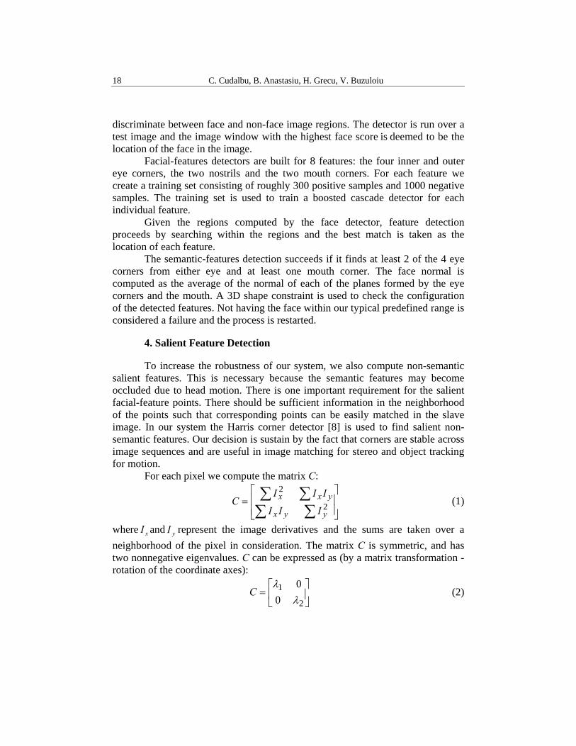
For each pixel we compute the matrix C:
⎥⎥⎦
⎤
⎢⎢⎣
⎡=
∑∑∑∑
2
2
yyx
yxx
III
IIIC (1)
where xI and yI represent the image derivatives and the sums are taken over a neighborhood of the pixel in consideration. The matrix C is symmetric, and has two nonnegative eigenvalues. C can be expressed as (by a matrix transformation - rotation of the coordinate axes):
⎥⎦
⎤⎢⎣
⎡=
2
10
0λ
λC (2)
Using stereo vision for real-time head-pose and gaze estimation 19
If 021 >≥ λλ , then, there is a corner pattern in the neighborhood, with two principal directions. The eigenvectors of C encode the directions, and the eigenvalues of C encode the variational strength.
For each matrix we compute: ( ) ( )2det CtracekC ⋅− (3)
where k is a small number (0.04, as suggested by Harris). Typically we take the first 30 to 50 pixels which have the value given by the equation above larger than a threshold. These pixels represent the salient non-semantic features. The number of features (30 to 50) that we have chosen limits the computational complexity, allowing a frame rate of approximately 30Hz on a Pentium 4 PC at 3Ghz.
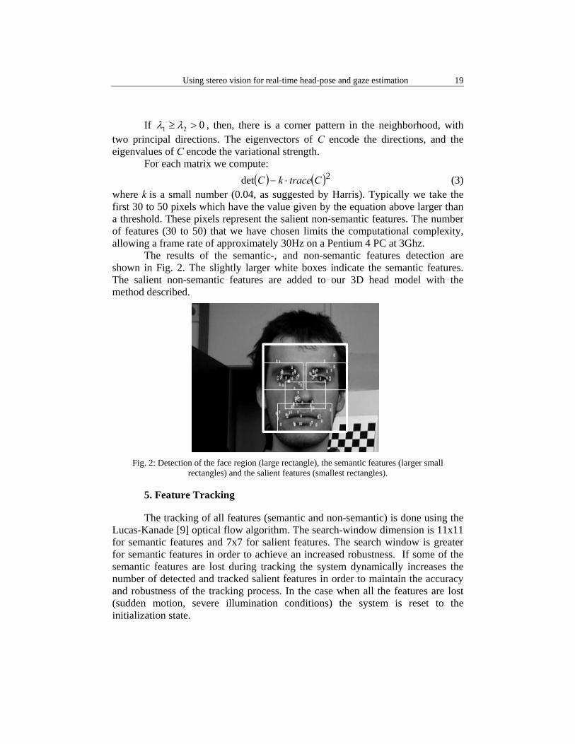
The results of the semantic-, and non-semantic features detection are shown in Fig. 2. The slightly larger white boxes indicate the semantic features. The salient non-semantic features are added to our 3D head model with the method described.
Fig. 2: Detection of the face region (large rectangle), the semantic features (larger small
rectangles) and the salient features (smallest rectangles).
5. Feature Tracking
The tracking of all features (semantic and non-semantic) is done using the Lucas-Kanade [9] optical flow algorithm. The search-window dimension is 11x11 for semantic features and 7x7 for salient features. The search window is greater for semantic features in order to achieve an increased robustness. If some of the semantic features are lost during tracking the system dynamically increases the number of detected and tracked salient features in order to maintain the accuracy and robustness of the tracking process. In the case when all the features are lost (sudden motion, severe illumination conditions) the system is reset to the initialization state.
C. Cudalbu, B. Anastasiu, H. Grecu, V. Buzuloiu 20
6. 3D Reconstruction
Despite the wealth of information contained in a single image, the depth of a scene point along the correspondence projection ray is not directly accessible in a single image.
With at least two images, however, depth can be measured through triangulation. For this we must find matching features in the master and slave images. The features in the master image are tracked as described above. These features need to be identified in the slave image. The typical approach is to search on the epipolar line the features in the slave image by using a correlation algorithm. To this principle approach several constraints were added in order to reduce the computational complexity:
1. Search on the epipolar by using a depth constraint 2. Predict the regions of interest for the features once at least 5 of them
where matched correctly. By only fixating a threshold on the correlation value the validation may
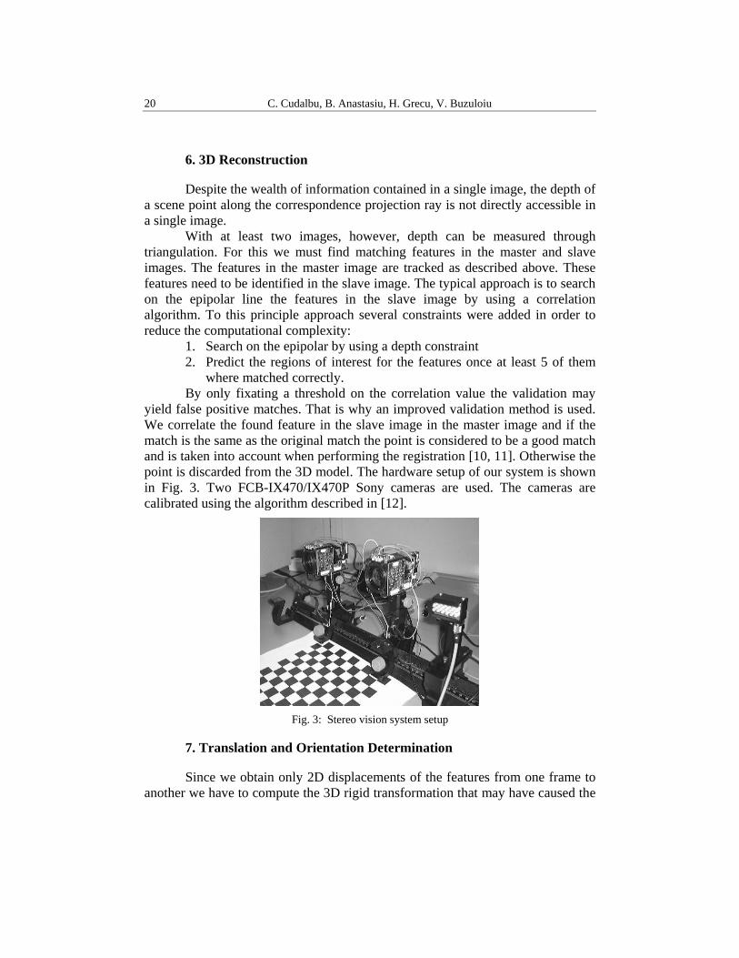
yield false positive matches. That is why an improved validation method is used. We correlate the found feature in the slave image in the master image and if the match is the same as the original match the point is considered to be a good match and is taken into account when performing the registration [10, 11]. Otherwise the point is discarded from the 3D model. The hardware setup of our system is shown in Fig. 3. Two FCB-IX470/IX470P Sony cameras are used. The cameras are calibrated using the algorithm described in [12].
Fig. 3: Stereo vision system setup
7. Translation and Orientation Determination
Since we obtain only 2D displacements of the features from one frame to another we have to compute the 3D rigid transformation that may have caused the
Using stereo vision for real-time head-pose and gaze estimation 21
displacement. This problem is known as the absolute orientation problem. For this purpose we chose a popular algorithm developed by Arun, Huang and Blostein [13, 14] that is based on computing the singular value decomposition (SVD) of a derived matrix.
Problem description Assume there exists two corresponding sets of points { }im and { }id , i =
1…N, such that they are related by iii VTRmd ++= (4)
where R is a standard 3x3 rotation matrix, T is a 3D translation vector and iV is the noise vector. Solving for the optimal transformations R,T that map the set { }im onto { }id typically requires minimizing the least squares error criterion:
∑=
−−=ΣN
iii TmRd
1
22 ˆˆ (5)
A solution involving the SVD of a matrix By noticing that the point sets should have the same centroid at the correct
solution, the rotation component is found first by analyzing point sets after their translation to the origin. A 3x3 correlation matrix given by
∑=
=N
i
Ticic dmH
1,, (6)
is computed based on these new centered point sets. Its singular value decomposition TUAVH = , is determined. The optimal rotation matrix is then
TVUR = . The optimal translation is found as the one that aligns the centroid of the set { }id with the centroid of the optimally rotated set { }im
mRdT ˆ−= (7)
8. Iris center detection
The 2D iris center position is detected using a fast modified Hough transform [15] approach. The search area for iris/pupil is reduced only to the eye regions detected with the face and facial features detection module. The detection has three main components:
edge detector using a compass operator Hough transform module based on circular arcs templates Iris center selection module
C. Cudalbu, B. Anastasiu, H. Grecu, V. Buzuloiu 22
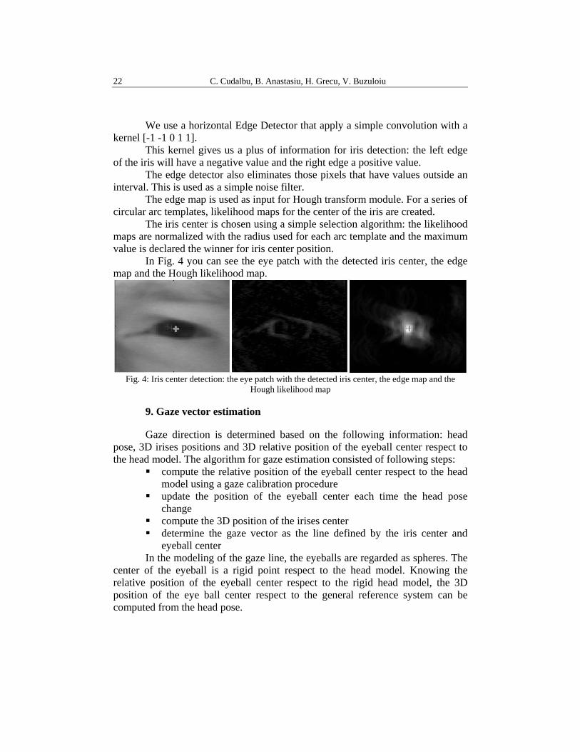
We use a horizontal Edge Detector that apply a simple convolution with a kernel [-1 -1 0 1 1].
This kernel gives us a plus of information for iris detection: the left edge of the iris will have a negative value and the right edge a positive value.
The edge detector also eliminates those pixels that have values outside an interval. This is used as a simple noise filter.
The edge map is used as input for Hough transform module. For a series of circular arc templates, likelihood maps for the center of the iris are created.
The iris center is chosen using a simple selection algorithm: the likelihood maps are normalized with the radius used for each arc template and the maximum value is declared the winner for iris center position.
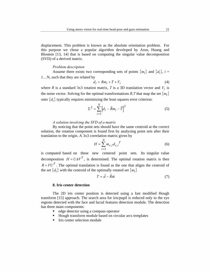
In Fig. 4 you can see the eye patch with the detected iris center, the edge map and the Hough likelihood map.
Fig. 4: Iris center detection: the eye patch with the detected iris center, the edge map and the
Hough likelihood map
9. Gaze vector estimation
Gaze direction is determined based on the following information: head pose, 3D irises positions and 3D relative position of the eyeball center respect to the head model. The algorithm for gaze estimation consisted of following steps:
compute the relative position of the eyeball center respect to the head model using a gaze calibration procedure
update the position of the eyeball center each time the head pose change
compute the 3D position of the irises center determine the gaze vector as the line defined by the iris center and
eyeball center In the modeling of the gaze line, the eyeballs are regarded as spheres. The
center of the eyeball is a rigid point respect to the head model. Knowing the relative position of the eyeball center respect to the rigid head model, the 3D position of the eye ball center respect to the general reference system can be computed from the head pose.
Using stereo vision for real-time head-pose and gaze estimation 23
The gaze calibration phase consists of determining the eyeball’s center for both eyes relative to the head model. The calibration video consists of a series of frames where the user keeps looking at a fixed point (the master camera) and rotates his head without obstructing the fixed point. The head movements are composed by yaw and then by pitch rotations.
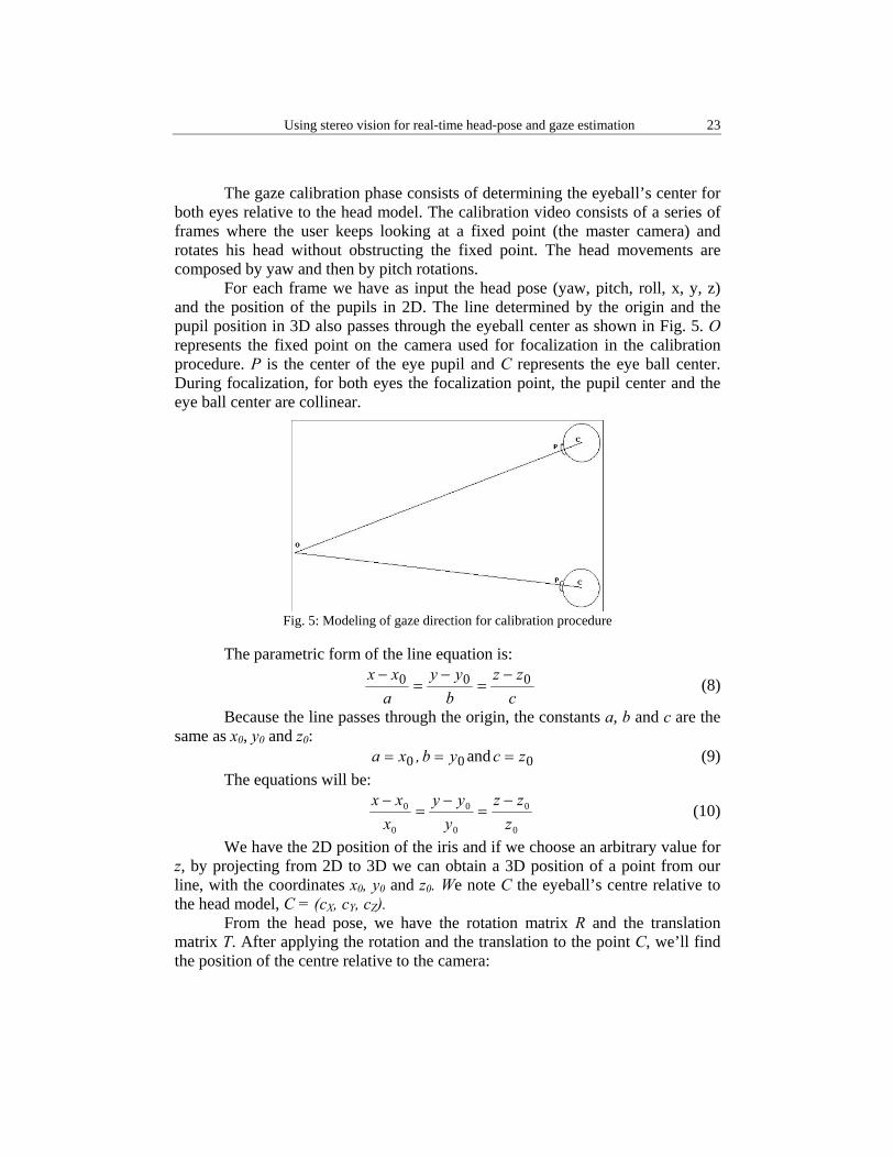
For each frame we have as input the head pose (yaw, pitch, roll, x, y, z) and the position of the pupils in 2D. The line determined by the origin and the pupil position in 3D also passes through the eyeball center as shown in Fig. 5. O represents the fixed point on the camera used for focalization in the calibration procedure. P is the center of the eye pupil and C represents the eye ball center. During focalization, for both eyes the focalization point, the pupil center and the eye ball center are collinear.
Fig. 5: Modeling of gaze direction for calibration procedure
The parametric form of the line equation is:
czz
byy
axx 000 −
=−
=−
(8)
Because the line passes through the origin, the constants a, b and c are the same as x0, y0 and z0:
0xa = , 0yb = and 0zc = (9) The equations will be:
0
0
0
0
0
0
zzz
yyy
xxx −
=−
=−
(10)
We have the 2D position of the iris and if we choose an arbitrary value for z, by projecting from 2D to 3D we can obtain a 3D position of a point from our line, with the coordinates x0, y0 and z0. We note C the eyeball’s centre relative to the head model, C = (cX, cY, cZ).
From the head pose, we have the rotation matrix R and the translation matrix T. After applying the rotation and the translation to the point C, we’ll find the position of the centre relative to the camera:
C. Cudalbu, B. Anastasiu, H. Grecu, V. Buzuloiu 24
TRCC +=' (11) The equations become:
0
0'
0
0'
0
0'
zzc
yyc
xxc zyx −
=−
=−
(12)
If we consider z0 = 1, the equations become:
'
0
'
0
'
zyx c
yc
xc
== (13)
But
⎪⎪⎩
⎪⎪⎨
⎧
+⋅+⋅+⋅=
+⋅+⋅+⋅=
+⋅+⋅+⋅=
2222120'
1121110'
0020100'
trcrcrcc
trcrcrcc
trcrcrcc
zyxz
zyxy
zyxx
(14)
so the final form of the equations will be:
⎪⎩
⎪⎨⎧
⋅−=⋅−⋅+⋅−⋅+⋅−⋅
⋅−=⋅−⋅+⋅−⋅+⋅−⋅
201122201121010200
200022200121000200
)()()(
)()()(
tytcrrycrrycrry
txtcrrxcrrxcrrx
zyx
zyx (15)
If we consider n frames, we’ll have 2n equations with 3 variables (cx, cy and cz). Our linear system of equations will be over-determined. The unknown variables can be computed by doing a least squares fit, which minimizes the sum of the squares of the deviations of the data from the model.
We want to find vector x, the solution of the linear set bA =⋅ x , where:
⎟⎟⎟
⎠
⎞
⎜⎜⎜
⎝
⎛
=
z
y
x
c
cc
x ;
⎟⎟⎟⎟⎟⎟⎟⎟
⎠
⎞
⎜⎜⎜⎜⎜⎜⎜⎜
⎝
⎛−⋅−⋅−⋅−⋅−⋅−⋅
=
...
...
...
...122201121010200
022200121000200
rryrryrryrrxrrxrrx
A ;
⎟⎟⎟⎟⎟⎟⎟⎟
⎠
⎞
⎜⎜⎜⎜⎜⎜⎜⎜
⎝
⎛⋅−⋅−
=
.
.
.
.201
200
tyttxt
b (16)
The problem reduces in solving a linear least-squares system by singular value decomposition method.
Note that for calibration we use only one camera reducing the computational time requested by processing one pair of images.
After the calibration step the 3D eyeball center is updated each frame with the head pose.
Using the pupil center detection algorithm described in the chapter above, we compute the 2D coordinates of the two irises in each master and slave images. Using triangulation we determine the 3D positions of the two irises center.
Using stereo vision for real-time head-pose and gaze estimation 25
The 3D gaze vector is computed as the vector which crosses through the eyeball center and iris center. We compute the gaze vector for each eye.
10. Results
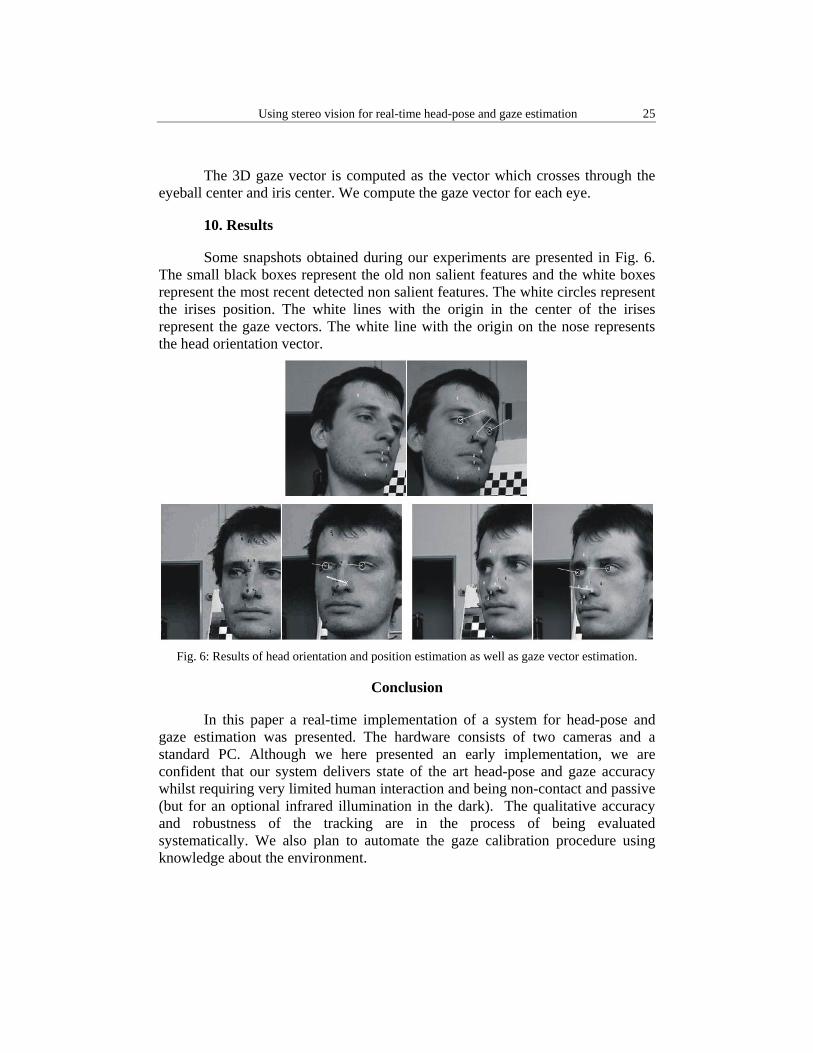
Some snapshots obtained during our experiments are presented in Fig. 6. The small black boxes represent the old non salient features and the white boxes represent the most recent detected non salient features. The white circles represent the irises position. The white lines with the origin in the center of the irises represent the gaze vectors. The white line with the origin on the nose represents the head orientation vector.
Fig. 6: Results of head orientation and position estimation as well as gaze vector estimation.
Conclusion
In this paper a real-time implementation of a system for head-pose and gaze estimation was presented. The hardware consists of two cameras and a standard PC. Although we here presented an early implementation, we are confident that our system delivers state of the art head-pose and gaze accuracy whilst requiring very limited human interaction and being non-contact and passive (but for an optional infrared illumination in the dark). The qualitative accuracy and robustness of the tracking are in the process of being evaluated systematically. We also plan to automate the gaze calibration procedure using knowledge about the environment.
C. Cudalbu, B. Anastasiu, H. Grecu, V. Buzuloiu 26
R E F E R E N C E S
1. A. Petland, “Looking at People: Sensing for Ubiquitous and Wearable Computing”, IEEE Transactions On Pattern Analysis And Machine Intelligence, Vol. 22, No. 1, January 2000
2. http://www.polhemus.com/ 3. http://www.smarteye.se/ 4. M. A. Fischler and R. C. Bolles, “Random Sample Consensus: A Paradigm for Model Fitting
with Applications to Image Analysis and Automated Cartography”, Comm. of the ACM, Vol. 24, pp. 381-395, 1981
5. Yoshio Matsumoto and Alexander Zelinsky, “An Algorithm for Real-time Stereo Vision Implementation of Head Pose and Gaze Direction Measurement”, IEEE Fourth International Conference on Face and Gesture Recognition (FG'2000), pp. 499-505, Grenoble, France, March 28-30, 2000
6. P. Viola and M. Jones, “Rapid object detection using a boosted cascade of simple features”, IEEE Computer Society Conference on Computer Vision and Pattern Recognition, 2001
7. Y. Freund and R.E. Schapire, “A decision-theoretic generalization of on-line learning and an application to boosting”, 2nd European Conference on Computational Learning Theory, 1995
8. C. Harris and M. Stephens, “A combined corner and edge detector”, Fourth Alvey Vision Conference, pp.147-151, 1988
9. S. Baker and I. Matthews, “Lucas-Kanade 20 Years On: A Unifying Framework”, tech. report CMU-RI-TR-02-16, Robotics Institute, Carnegie Mellon University, July 2002
10. O. Faugerard, “Three-Dimensional Computer Vision”, The MIT Press, 1993 11. O. Faugeras, B. Hotz and L. Moll, “Real-time correlation based stereo algorithm,
implementations and applications”, INRIA Reseach Report 2013, August 1993 12. Z. Zhang, “A Flexible New Technique for Camera Calibration”, Technical Report MSR-TR-
98-71, December 1998 13. K. S. Arun, T. S. Huang and S. D. Blostein, “Least-Squares Fitting of Two 3D Point Sets”,
IEEE Transactions on Pattern Analysis and Machine Intelligence, Vol. 9, pp. 698-700, 1987
14. A. Lorusso, D.W. Eggert and R.B. Fisher, “A Comparison of Four Algorithms for Estimating 3-D Rigid Transformations”, British Machine Vision Conference, 1995 British conference on Machine vision, Vol. 1, pp.237-246, Birmingham, United Kingdom, July 1995
15. P.V.C. Hough, “Machine Analysis of Bubble Chamber Pictures”, International Conference on High Energy Accelerators and Instrumentation, CERN, 1959