BULETINUL INSTITUTULUI POLITEHNIC DIN IAŞI Publicat de Universitatea Tehnică „Gheorghe Asachi” din Iaşi Volumul 63 (67), Numărul 2, 2017 Secţia ELECTROTEHNICĂ. ENERGETICĂ. ELECTRONICĂ SYMMETRICAL COMPONENTS EVALUATION IN REAL- TIME BY SEBASTIAN ARĂDOAEI * and OLGA PLOPA Technical University “Gheorghe Asachi” of Iaşi, Faculty of Electrical Engineering Received: April 25, 2017 Accepted for publication: May 26, 2017 Abstract. Using Symmetrical components methodology, unbalanced system conditions, like those caused by common fault types may be visualized and analyzed. In order to calculate direct and inverse components, the phasors must be multiplied by the phasor rotation operator a =e j2π/3 . The classical mathematical expressions associated with this issue are well-suited especially in phasic calculus. However, in the time domain, the authors do not offer practical solutions. The paper presents concrete ways to solve the problem of rotating a sinusoidal size in real-time using PSpice and Matlab Simulink software. Based on these, the real and the inverse components of an unbalanced three-phase system are determined in real time. Key words: symmetrical components; PSpice; Simulink; electrical machines. 1. Introduction Symmetrical components is a methodology discovered by Charles Legeyt Fortescue. He demonstrated that any set of unbalanced three-phase quantities could be expressed as the sum of three symmetrical sets of balanced phasors (Fortescue, 1918). Using this tool, unbalanced system conditions, like * Corresponding author: e-mail: [email protected]
Transcript
BULETINUL INSTITUTULUI POLITEHNIC DIN IAŞI Publicat de
Universitatea Tehnică „Gheorghe Asachi” din Iaşi Volumul 63 (67), Numărul 2, 2017
Secţia ELECTROTEHNICĂ. ENERGETICĂ. ELECTRONICĂ
SYMMETRICAL COMPONENTS EVALUATION IN REAL-TIME
BY
SEBASTIAN ARĂDOAEI* and OLGA PLOPA
Technical University “Gheorghe Asachi” of Iaşi, Faculty of Electrical Engineering
Received: April 25, 2017 Accepted for publication: May 26, 2017
Abstract. Using Symmetrical components methodology, unbalanced system conditions, like those caused by common fault types may be visualized and analyzed. In order to calculate direct and inverse components, the phasors must be multiplied by the phasor rotation operator a=ej2π/3. The classical mathematical expressions associated with this issue are well-suited especially in phasic calculus. However, in the time domain, the authors do not offer practical solutions. The paper presents concrete ways to solve the problem of rotating a sinusoidal size in real-time using PSpice and Matlab Simulink software. Based on these, the real and the inverse components of an unbalanced three-phase system are determined in real time.
Symmetrical components is a methodology discovered by Charles
Legeyt Fortescue. He demonstrated that any set of unbalanced three-phase quantities could be expressed as the sum of three symmetrical sets of balanced phasors (Fortescue, 1918). Using this tool, unbalanced system conditions, like *Corresponding author: e-mail: [email protected]
28 Sebastian Arădoaei and Olga Plopa
those caused by common fault types may be visualized and analyzed. The method of symmetrical components is usually used in power systems to simplify the analysis of unbalanced three-phase systems. In the most common case of three-phase system, the resulting symmetrical components are referred as direct (or positive), inverse (or negative) and homopolar (or zero). The resulting transform equations are mutually linearly independent.
The basic idea is that an asymmetrical set of three phasors can be expressed as a linear combination of three symmetrical sets of phasors by means of a complex linear transformation.
The first application of the symmetrical components to the electrical machines was described by Lyon (1954). In addition, other authors have developed studies on the use of symmetrical components in the study of electric machines (White & Woodson, 1959; Harris et al., 1970; Paap, 2000).
A study on the possibility of using symmetrical components method in the analysis of induction machine behavior is presented in (Cociu & Cociu, 2014). Starting from the observation that induction machine is described by a system generally of nonlinear equations, the authors try to determine the circumstances in which this method can be used in studying the behavior of the induction machine.
Consider a three-phase (asymmetric) system of sinusoidal quantities with the same pulse ω, the amplitude and the initial phase having an arbitrary value, generally different for each voltage:
)γωsin(2)(
)γωsin(2)(
)γωsin(2)(
ccc
bbb
aaa
tVtv
tVtv
tVtv
(1)
These quantities can be mapped to their corresponding complex
phasors:
c
b
a
eV
eV
eV
cc
bb
aa
jγ
jγ
jγ
V
V
V
(2)
According to symmetrical components method, they can be expressed
The system is uniquely determined by the origin vectors:
aicbai
adcbad
V)/3VaVaV(V
V)/3VaVaV(V2
2
(4)
3/)VVV(V0 cba (5)
where: a is a phasor rotation operator which rotates a phasor vector counterclockwise by 120 degree.
From eq. (4), for the determination of the direct and inverse phase component of the three voltages we must multiply with a and a2. In the time domain it corresponds to phasing sinusoidal quantities vx(t) with 2π/3 or 4π/3 radians respectively. The same problem applied to two-dimensional sizes requires shifting.
2. Theoretical Part
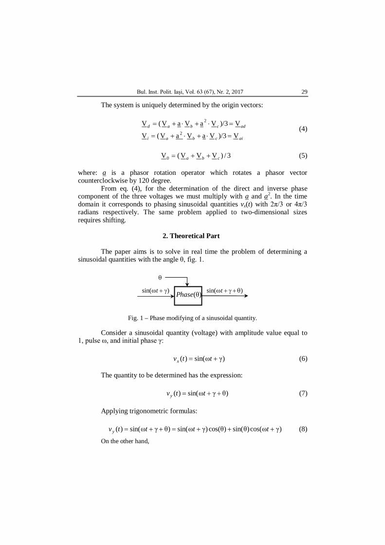
The paper aims is to solve in real time the problem of determining a
sinusoidal quantities with the angle θ, fig. 1.
Fig. 1 – Phase modifying of a sinusoidal quantity.
Consider a sinusoidal quantity (voltage) with amplitude value equal to 1, pulse ω, and initial phase γ:
)γωsin()( ttvx (6)
The quantity to be determined has the expression:
)θγωsin()( ttvy (7)
Applying trigonometric formulas:
)γωcos()θsin()θcos()γωsin()θγωsin()( ttttvy (8)
On the other hand,
)sin( t )sin( t
)θ(Phase
30 Sebastian Arădoaei and Olga Plopa
d[ ( )]1 d[sin(ω γ)] 1cos(ω γ) ,ω d ω d
xv tttt t
(9)
resulting:
d( )1( ) cos(θ) sin(θ) .ω d
xy x
vv t vt
(10)
Eq. (10) allows the sinusoidal quantities to be determined for the angle
θ starting from any sinusoidal size. Note that, pulse ω must be known. Otherwise it should be determined. When a machine is supplied from the network, the fundamental frequency is constant over time or over large time intervals. In the worst case, the frequency can be measured for a large interval of time and its value used as an input constant. This gives ω(t) = const = ω. (Cociu & Cociu, 2017).
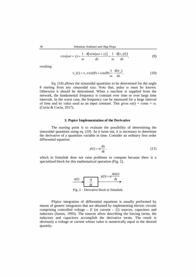
3. Pspice Implementation of the Derivative The starting point is to evaluate the possibility of determining the
sinusoidal quantities using eq. (10). As it turns out, it is necessary to determine the derivative of a quantities variable in time. Consider an ordinary first order differential equation:
txaty
dd)( . (11)
which in Simulink does not raise problems to compute because there is a specialized block for this mathematical operation (Fig. 2).
Fig. 2 – Derivative block in Simulink.
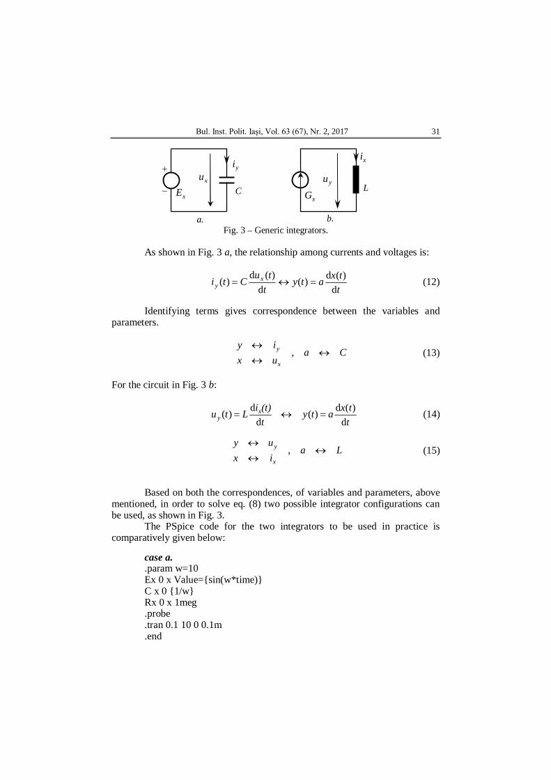
PSpice integration of differential equations is usually performed by means of generic integrators that are obtained by implementing electric circuits comprising controlled voltage – E (or current – G) sources, capacitors and inductors (Justus, 1993). The sources allow describing the forcing terms, the inductors and capacitors accomplish the derivative terms. The result is obviously a voltage or current whose value is numerically equal to the desired quantity.
As shown in Fig. 3 a, the relationship among currents and voltages is:
ttxaty
ttuCti x
y d)(d)(
d)(d)( (12)
Identifying terms gives correspondence between the variables and
parameters.
Cauxiy
x
y
, (13)
For the circuit in Fig. 3 b:
ttxaty
t(t)iLtu x
y d)(d)(
dd)( (14)
Laixuy
x
y
, (15)
Based on both the correspondences, of variables and parameters, above
mentioned, in order to solve eq. (8) two possible integrator configurations can be used, as shown in Fig. 3.
The PSpice code for the two integrators to be used in practice is comparatively given below:
case a. .param w=10 Ex 0 x Value={sin(w*time)} C x 0 {1/w} Rx 0 x 1meg .probe .tran 0.1 10 0 0.1m .end
Cxu
L
yi
yu
xi
.a .b
xGxE
32 Sebastian Arădoaei and Olga Plopa
case b. .param w=10 Gx 0 y Value={sin(w*time)} Lj y 0 {Ljj} Ry g y {1/w} .probe .tran 0.1 10 0 0.1m .end The case a is superior from both points of view, of integration time and
data output file size. This is due to the circuit topology description in PSpice where, even if the two electrical circuits contain the same number of nodes, PSpice description of case a comprises only two nodes where as the description in case b has three nodes.
This method of solving differential equations has been widely used for modeling and simulating the motion mass equation (Cociu & Cociu, 2011), (Cociu & Cociu, 2014).
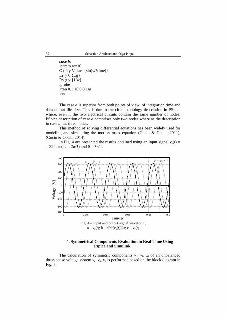
In Fig. 4 are presented the results obtained using an input signal vx(t) = = 324 sin(ωt – 2π/3) and θ = 3π/4.
Fig. 4 – Input and output signal waveform;
a – vx(t); b – d/dt[vx(t)]/; c – vy(t)
4. Symmetrical Components Evaluation in Real-Time Using Pspice and Simulink
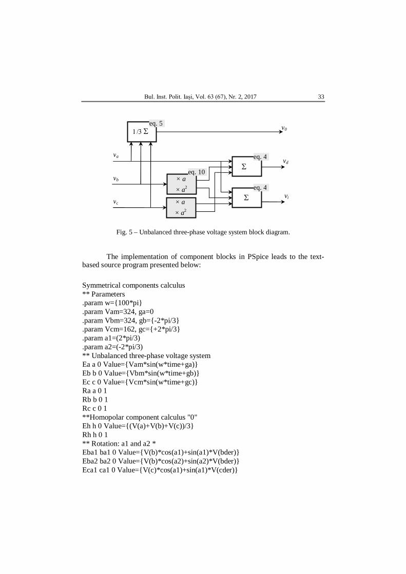
The calculation of symmetric components vd, vi, v0 of an unbalanced
three-phase voltage system va, vb, vc is performed based on the block diagram in Fig. 5.
Fig. 5 – Unbalanced three-phase voltage system block diagram. The implementation of component blocks in PSpice leads to the text-
based source program presented below:
Symmetrical components calculus ** Parameters .param w={100*pi} .param Vam=324, ga=0 .param Vbm=324, gb={-2*pi/3} .param Vcm=162, gc={+2*pi/3} .param a1=(2*pi/3) .param a2=(-2*pi/3) ** Unbalanced three-phase voltage system Ea a 0 Value={Vam*sin(w*time+ga)} Eb b 0 Value={Vbm*sin(w*time+gb)} Ec c 0 Value={Vcm*sin(w*time+gc)} Ra a 0 1 Rb b 0 1 Rc c 0 1 **Homopolar component calculus "0" Eh h 0 Value={(V(a)+V(b)+V(c))/3} Rh h 0 1 ** Rotation: a1 and a2 * Eba1 ba1 0 Value={V(b)*cos(a1)+sin(a1)*V(bder)} Eba2 ba2 0 Value={V(b)*cos(a2)+sin(a2)*V(bder)} Eca1 ca1 0 Value={V(c)*cos(a1)+sin(a1)*V(cder)}
va
vb
vc
× a × a2
× a × a2
vd
vi
v0 eq. 5
eq. 4
eq. 4
eq. 10
34 Sebastian Arădoaei and Olga Plopa
Eca2 ca2 0 Value={V(c)*cos(a2)+sin(a2)*V(cder)} Gb 0 bder Value={V(b)} Gc 0 cder Value={V(c)} Lb bder 0 {1/w} Lc cder 0 {1/w} ** Direct component calculus "d"* Ead ad 0 Value={(V(a)+V(ba1)+V(ca2))/3} Rad ad 0 1 ** indirect component calculus "i"* Eai ai 0 Value={(V(a)+V(ba2)+V(ca1))/3} Rai ai 0 1 ** .probe .tran 0.01 0.1 0.1m 0.1m uic .end
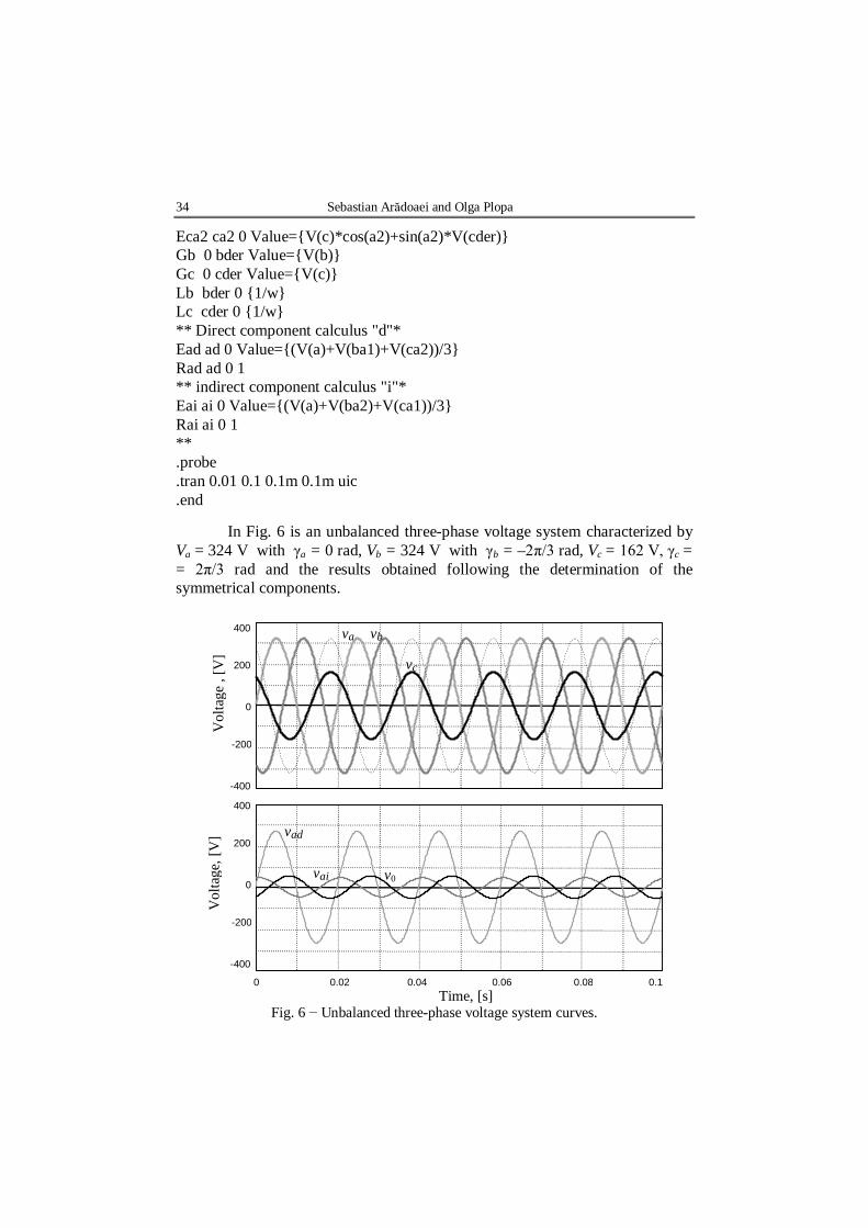
In Fig. 6 is an unbalanced three-phase voltage system characterized by
Va = 324 V with γa = 0 rad, Vb = 324 V with γb = –2π/3 rad, Vc = 162 V, γc = = 2π/3 rad and the results obtained following the determination of the symmetrical components.
Fig. 6 − Unbalanced three-phase voltage system curves.
Fig. 8 − Unbalanced three-phase voltage system curves.
-400
-200
0
200
400
0 0.0 0.0 0.0 0.0 0.
Vol
tage
, [V
]
Time, [s]
-400
-200
0
200
400
Vol
tage
, [V
]
va vb vc
vad
vai
v0
36 Sebastian Arădoaei and Olga Plopa
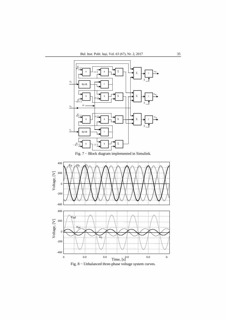
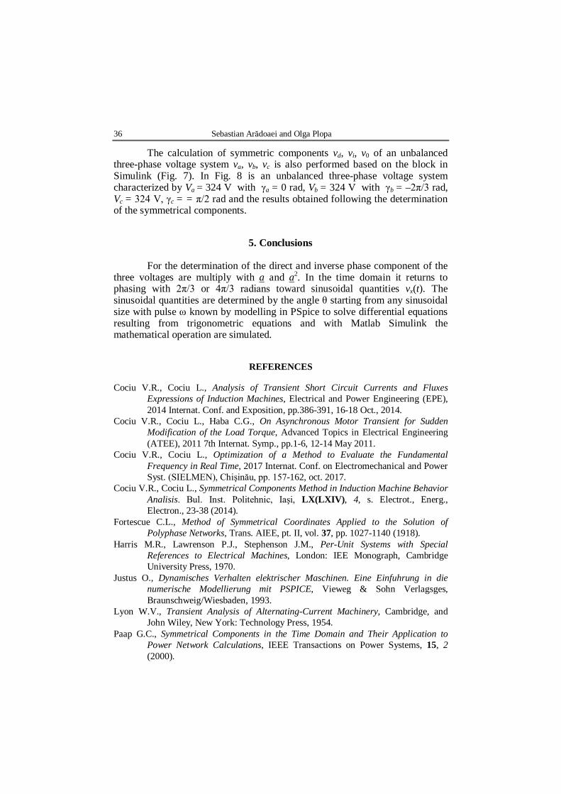
The calculation of symmetric components vd, vi, v0 of an unbalanced three-phase voltage system va, vb, vc is also performed based on the block in Simulink (Fig. 7). In Fig. 8 is an unbalanced three-phase voltage system characterized by Va = 324 V with γa = 0 rad, Vb = 324 V with γb = –2π/3 rad, Vc = 324 V, γc = = π/2 rad and the results obtained following the determination of the symmetrical components.
5. Conclusions For the determination of the direct and inverse phase component of the
three voltages are multiply with a and a2. In the time domain it returns to phasing with 2π/3 or 4π/3 radians toward sinusoidal quantities vx(t). The sinusoidal quantities are determined by the angle θ starting from any sinusoidal size with pulse ω known by modelling in PSpice to solve differential equations resulting from trigonometric equations and with Matlab Simulink the mathematical operation are simulated.
REFERENCES
Cociu V.R., Cociu L., Analysis of Transient Short Circuit Currents and Fluxes Expressions of Induction Machines, Electrical and Power Engineering (EPE), 2014 Internat. Conf. and Exposition, pp.386-391, 16-18 Oct., 2014.
Cociu V.R., Cociu L., Haba C.G., On Asynchronous Motor Transient for Sudden Modification of the Load Torque, Advanced Topics in Electrical Engineering (ATEE), 2011 7th Internat. Symp., pp.1-6, 12-14 May 2011.
Cociu V.R., Cociu L., Optimization of a Method to Evaluate the Fundamental Frequency in Real Time, 2017 Internat. Conf. on Electromechanical and Power Syst. (SIELMEN), Chişinău, pp. 157-162, oct. 2017.
Fortescue C.L., Method of Symmetrical Coordinates Applied to the Solution of Polyphase Networks, Trans. AIEE, pt. II, vol. 37, pp. 1027-1140 (1918).
Harris M.R., Lawrenson P.J., Stephenson J.M., Per-Unit Systems with Special References to Electrical Machines, London: IEE Monograph, Cambridge University Press, 1970.
Justus O., Dynamisches Verhalten elektrischer Maschinen. Eine Einfuhrung in die numerische Modellierung mit PSPICE, Vieweg & Sohn Verlagsges, Braunschweig/Wiesbaden, 1993.
Lyon W.V., Transient Analysis of Alternating-Current Machinery, Cambridge, and John Wiley, New York: Technology Press, 1954.
Paap G.C., Symmetrical Components in the Time Domain and Their Application to Power Network Calculations, IEEE Transactions on Power Systems, 15, 2 (2000).
White D.C., Woodson H., Electro Mechanical Energy Conversion, New York and Chapman & Hall, London: John Wiley & Sons, 1959.
EVALUAREA COMPONENTELOR SIMETRICE ÎN TIMP REAL
(Rezumat)
Folosind metodologia componentelor simetrice, pot fi vizualizate și analizate
condițiile de sistem dezechilibrat, cum ar fi cele cauzate de defecțiuni comune. Pentru a calcula componentele directe și inverse, fazorii trebuie înmulțiți cu operatorul de rotație a fazorului a = ej2π/3. Expresiile matematice clasice asociate cu această problemă sunt potrivite în special în calculul fazorilor. Cu toate acestea, în domeniul timpului, autorii nu oferă soluții practice. Lucrarea prezintă modalități concrete de a rezolva problema rotirii unei mărimi sinusoidale în timp real folosind software-ul PSpice și Matlab Simulink. Pe baza acestora sunt determinate în timp real componentele reale și inverse ale unui sistem trifazat dezechilibrat.